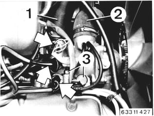
Vehicles before change point in 1982 REMOVING AND INSTALLING CYLINDER HEAD Disconnect ground wire at battery. Remove air cleaner housing 13 71 000. Drain coolant. Installation: Bleed cooling system 17 00 039. Detach warm water hoses (1 and 2). Pull off wires on temperature transmitter. Disconnect plug (3).  13 71 000 13 71 000 17 00 039 17 00 039
|  |
Up to 1980 Models: Detach exhaust pipes from reactor. Detach exhaust support on transmission. Installation: Install support to be without stress. Check gaskets, replacing if necessary. | 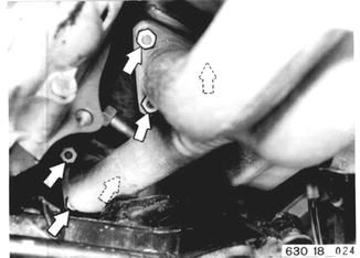 |
Detach pipe lines and pull off from exhaust filter. | 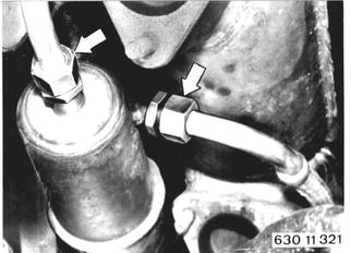 |
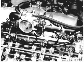
Remove cylinder head cover 11 12 000. Pull off plug connectors and remove distributor cap. Pull off plugs from fuel injectors 1 ... 6 and plug (2). Disconnect ground wire (3). Remove accelerator linkage (4). Pull off vacuum hoses from throttle housing and EGR line. Installation: Adjust accelerator cable 35 41 421.  11 12 000 11 12 000 * See Specifications * See Specifications
|  |
Detach water hose (5) on throttle housing. Loosen clamp (6). Pull off wires from oil pressure switch. Version with Auxiliary Air Valve: Pull off wires from auxiliary air valve. | 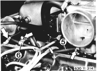 |
Loosen holder (9) and clamp (10). Pull off vacuum hoses (11 ... 14). Installation: 11 red from EGR valve/red elec. switch valve 12 blue from EGR valve/pressure converter 13 white from collector/white elec. switch valve Also refer to hose routing plan. Detach vacuum hose (15). Pull off plug (16) from cold start valve. Version with Automatic Transmission: Detach accelerator cable and take off holder from collector. | 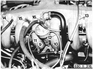 |
Detach fuel hoses (23 and 24). Installation: Hose (23) from fuel filter to ring line. Hose (24) from pressure regulator to return line. For BMW 633 CSi: Detach fuel feed and return lines from pressure regulator and/or pipe. | 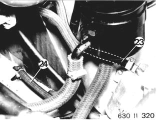 |
Pull off plugs (20 ... 22). Lift out wire harness from clamps. | 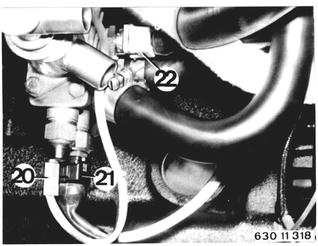 |
Pull out wire harness through opening in intake neck upward. | 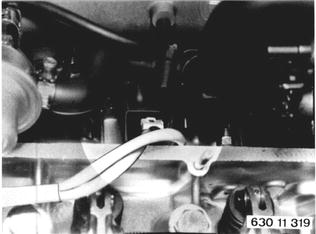 |
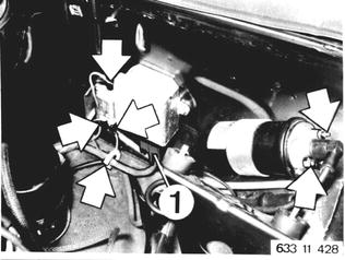
From 1980 Models: Remove heat shield and catalytic converter 18 00 020. Only 1980 Models: Remove water tank. Pull off plug (1). Pull off plugs on resistors and detach wire harness.  18 00 020 18 00 020
|  |
Disconnect ground wire (1). Pull off plugs (1 ... 6) from fuel injectors and disconnect wire harness. | 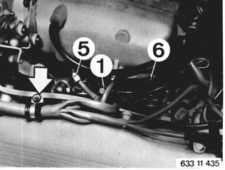 |
Pull off wire (1). Pull off wires on oil pressure switch. Detach vacuum hoses (2 and 3). Loosen clamps (4) and take off fuel lines (5) as well as the wire harness. | 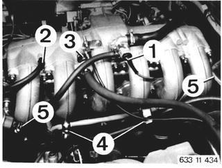 |
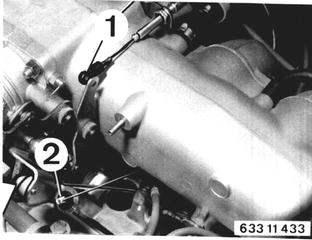
Disconnect accelerator linkage. Automatic Transmission: Detach accelerator cable (1). Tempomat Speed Cruise Control: Disconnect accelerator cable (2). Installation: Adjust accelerator linkage 35 41 421. Adjust accelerator cable 24 00 004.  * See Specifications * See Specifications 24 00 004 24 00 004
|  |
Detach hose (3). Pull off wires on throttle switch. | 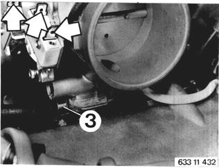 |
Remove intake pipe of cylinder no. 6. Place wire harness aside. | 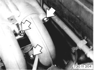 |
Installation: Replace gasket, cutting off gasket behind the staybolt. | 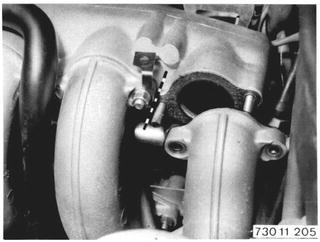 |
All Models: Detach coolant hoses (17 ... 19). Installation: Be careful not to mix up hoses. Bottom hose (18) from cylinder head. Top hose (19) to return line. | 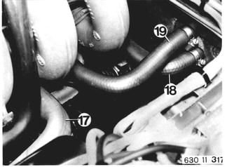 |
 |
|
Installation: Install chain that dowel pin (1) is located at bottom left. Bore in sprocket must align with tapped bore and cast tab. | 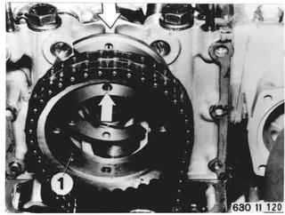 |
Loosen cylinder head bolts one after the other. Unscrew and remove 4 cylinder head bolts. Install locating pins to prevent movement or turning of rocker arm shafts. Take off cylinder head. | 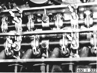 |
Installation: Make sure there is no oil in cavities, since otherwise bolts would not exert sufficient force on cylinder head even when tightened to specified torque. In addition, crankcase could be cracked. Clean cylinder head bolts and apply a light coat of oil on threads and bearing surface of bolts´ heads. Always replace cylinder head gasket. Tighten bolts in order of 1 through 14 to specified torque¹).  ¹) See Specifications ¹) See Specifications
| 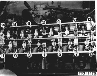 |
Tighten bolts in three steps: Step 1 - 34 to 44 Nm (25 to 32 ft.lbs.) Step 2 - 67 to 71 Nm (49 to 51 ft.lbs.) Step 3 - 75 to 81 Nm (54 to 59 ft.lbs.) Run engine to operating temperature. Tighten bolts by torque angle of 25±5°, regardless of engine temperature. Cylinder head is not tightened again after driving car 1,000 km (600 miles). Adjust valve play 11 34 004. Adjust ignition timing 12 11 004. Adjust engine idle speed and CO level 13 00 054. Important: Valves must be adjusted additionally if cylinder head or valves had been replaced, valves or valve seats had been machined.  11 34 004 11 34 004 12 11 004 12 11 004 13 00 054 13 00 054
|  |
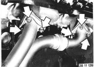
Vehicles after change point in 1982 REMOVING AND INSTALLING CYLINDER HEAD Unscrew exhaust pipes on manifolds and pipe clamp on transmission. Installation: Check gaskets, replacing if necessary. Coat studs with copper paste "CRC"**. Replace self-locking nuts. Tightening torque*.  ** Source: HWB ** Source: HWB * See Specifications * See Specifications
|  |
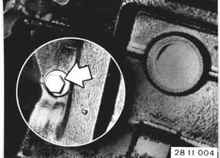
Unscrew plug and drain coolant. Disconnect battery ground lead. Installtion: Add coolant*** and bleed cooling system 17 00 039. Replace engine oil***.  17 00 039 17 00 039 *** See Service Information of Gr. 00 *** See Service Information of Gr. 00
|  |
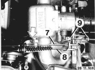
Disconnect accelerator cable (7), cruise control cable (8) and throttle cable (9). Installation: Adjust accelerator cable - see 35 41 421. Adjust cruise cable - see Group 65. Adjust throttle cable - see Gr. 24.  35 41 421 35 41 421
|  |
M 30 B 32: Pull off plug (2) and lift out wires. Pull out hoses (3 and 4). Loosen hose clamp (5). Disconnect wire. Unscrew nuts (6) and remove air cleaner with air flow sensor. | 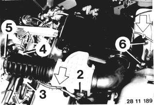 |
Pull off plug (1) and lift out relay. Disconnect wire harness. | 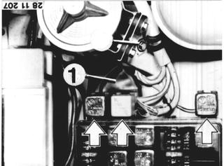 |
Pull off plugs. Disconnect fuel return line (8) and water hoses (10). | 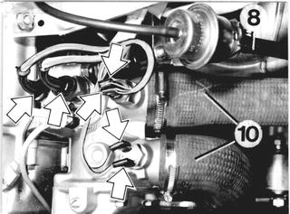 |
M 30 B 34: Pull off plug (2) and lift out wires. Pull off plug (3) and unscrew nut (4). Pull of hoses (5 ... 8). Disconnect wire (9). Open clamp (10). Loosen hose clamp (11). Unscrew nuts (12) and remove air cleaner with air flow sensor. | 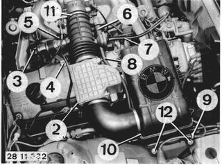 |
Unscrew engine wire harness (10) on positive pole. Pull off plug (11). Lift out relays (12 ... 14). Lift out diagnosis socket (15). Unscrew clamp (16). Disconnect wire harness. | 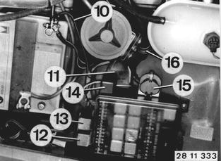 |
Pull off plugs. Disconnect fuel return line (17) and water hoses (18 and 19). | 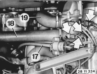 |
All Models: Disconnect fuel feed line and heater hoses (8 and 9). Disconnect water hoses for expansion tank. Pull of vacuum hose. | 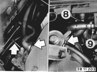 |
Remove screw (13). Disconnect wires (14 and 15) on alternator and starter. Lift out and disconnect plug (16). | 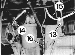 |
Unscrew ignition lead tube (10) and distributor cap. Disconnect diagnosis socket. Remove screes (11). Disconnect DME plugs (13 and 17). Pull off hose (15) and take off cylinder head cover. Installation: Make sure gasket fits correctly. | 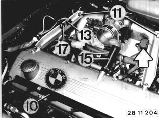 |
Connect DME plugs for reference mark and speed sensor signals, that gray plug (17) is connected with that plug which is marked with a ring. |  |
Pull off plugs on fuel injectors (1 ... 6), cold start valve (7), idle positioner (8), oil pressure switch (9) and throttle (10). Unscrew clamp (11) and ground lead (12). Disconnect engine wire harness and place aside to the right. | 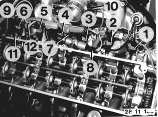 |
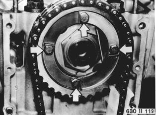
Remove upper timing case cover 11 14 100. Remove chain tensioner piston 11 31 000. Open lockplates. Unscrew sprocket. Note: Lockplates are not used again. Tightening torque*.  11 14 100 11 14 100 11 31 000 11 31 000 * See Specifications * See Specifications
| 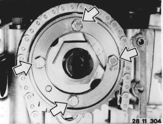 |
Installation: Install timing chain that dowel pin (1) is at bottom left when tapped bores are perpendicilar to the engine. | 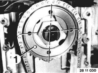 |
Unscrew cylinder head bolts in order of 14 through 1. Insert Special Tools 11 1 063 as shown in picture, to prevent moving or turning of rocker arm shafts. Lift off cylinder head. | 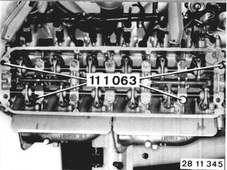 |
Installation: Keep oil out of cavities, since otherwise bolts would not exert sufficient pressure on the cylinder head even though they are thightened to correct torque. Engine block could also be cracked. Clean cylinder head bolts. Lubricate threads and bearing surfaces of bolt heads with a light coat of oil. Replace cylinder head gasket - see 11 12 101.  11 12 101 11 12 101
| 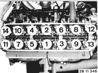 |
Tighten bolts in order of 1 through 14 to correct torque* in three steps. Important! New cylinder head bolts without collar (better quality): First tighten bolts 1 ... 6 with 60 ± 2 Nm (43.4 ± 1.4 ft. lbs.) - remove Special Tools 11 1 063 - then tighten bolts 7 ... 14 in first step.  * See Specifications * See Specifications
|  |
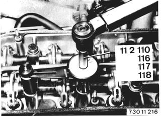
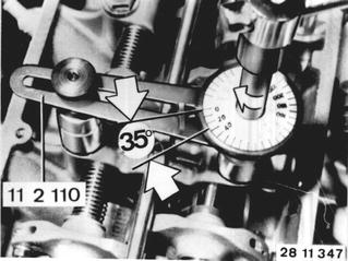
Adjust valve clearance - see 11 34 004. Only M 30 B 32: Adjust engine idle speed/CO - see Group 13. Tighten cylinder head bolts to torque angle* with Special Tool 11 2 110 regardless of engine temperature in the third step (cylinder head cover removed again after engine was run warm).  11 34 004 11 34 004 * See Specifications * See Specifications
|  |