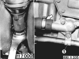
REMOVING AND INSTALLING CAMSHAFT Remove cylinder head 11 12 100. Up to 1980 Models: Unscrew nut on EGR valve with Special Tool 11 7 000. Detach line (1). Detach coolant hose.  11 12 100 11 12 100
|  |
Mount cylinder head on Special Tool 11 1 060. Detach oil line. Installation: Watch location of seals (2 and 3). | 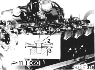 |
Important: Oil line must be installed that oil bores will give off spray between rocker arms and cams of intake and exhaust valves. A = 180±0.5 mm (7.087±0.020´´) in forward direction. | 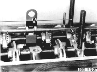 |
Adjust valve clearance of all cylinder to maximum value. Improtant: Turn camshaft from TDC position of cylinder 1 toward intake by distance A = about 15 mm (0.590´´), before mounting Special Tool 11 1 060. | 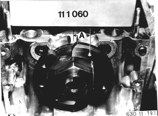 |
Mount Special Tool 11 1 060, moving rocker arms on intake side of cylinders 2 and 4 forward by about 7 mm (0.275´´). Important: To prevent any contact between valve discs, first tighten exhaust side nuts (1) to stop and then intake side nuts (2). Continue in reverse sequence after removing the special tool. | 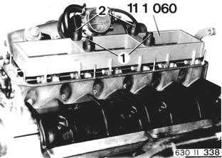 |
Unscrew bolts (4 and 5). Pull out camshaft. | 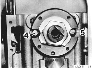 |
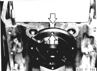
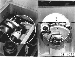
Installation: Camshaft must turn easily after guide plate is installed. Position cylinder 6 to overlap before removal of special tool. Threaded bore in flange must line up with cast tab. Installation: Adjust valve clearance 11 34 004.  11 34 004 11 34 004
|  |
Vehicles after change point in 1982 REMOVING AND INSTALLING CAMSHAFT - CYL. HEAD REMOVED - Mount Special Tool 11 1 060 on Special Tool 00 1 490. Mount cylinder head on special tool assembly. | 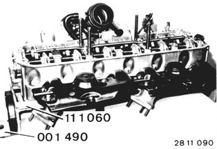 |
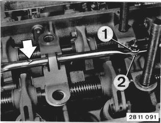
Unscrew oil line. Installation: Replace seals (1 and 2). Mount oil line that arrow faces forward. Tightening torque*.  * See Specifications * See Specifications
|  |
Adjust valve clearance of all valves to the greatest value. Turn camshaft approx. 15° and mount Special Tool 11 1 061. | 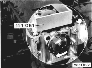 |
Push rocker arms of cylinder 2 and 4 (intake) forward and align special tool in such a manner that tabs rest on eccentrics of rocker arms. Important! To avoid contact between valve heads, first tighten nuts (3) on exhaust side to stop and then tighten nuts (4) on intake side slightly. Procedures are inversed when taking off the special tool. | 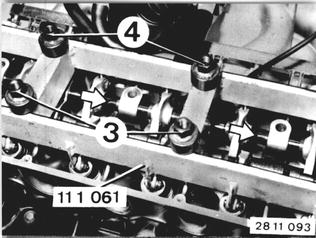 |
Unscrew bolts (5). Pull out camshaft. Important! If nuts (4) on the intake side have to be retightened, make sure that contact between valve heads is avoided. | 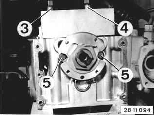 |
Instrallation: It must be possible to turn the camshaft easily after installation of the guide plate. Set valves of cylinder no. 6 to overlap before releasing the special tool. Tapped bore in flange must be aligned with the cast boss. Installation: Adjust valve clearance 11 34 004. Important! Install a hexagon nut with a drive pin** as a service sector solution for a camshaft with a damaged drive pin.  11 34 004 11 34 004 ** See Service Information of Gr. 11 ** See Service Information of Gr. 11
|  |