REMOVING AND INSTALLING INPUT AND OUTPUT SHAFTS Revmove transmission case front section 23 11 010. Remove transmission case rear section 23 11 022. Swing output shaft down. Pull 5th gear off of layshaft with Special Tool 23 0 080. Bearing inner race is also pulled off. Pressing off force 9 ... 10 t.  23 11 010 23 11 010 23 11 022 23 11 022
| 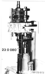 |
Important: To avoid damage on 3rd gear while pulling off 5th gear, make sure that there is always play (S) between 3rd gear and layshaft. If necessary, push up output shaft. | 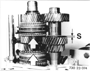 |
Pull bearing race off of output shaft with Special Tools 23 1 100 and 00 7 500. | 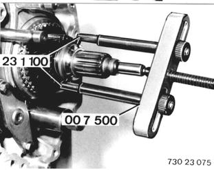 |
Remove washer (1) and ball (2). | 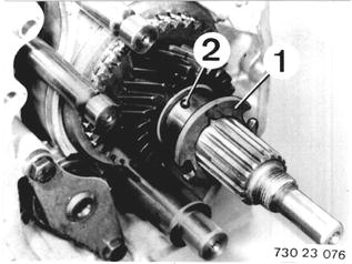 |
Pull off 5th gear with synchromesh ring and split needle bearing. | 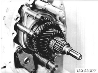 |
Remove rollers from selector shaft. Knock pin (3) out of selector shaft, holding shaft tight. Pull out selector shaft toward rear. Remove selector arm. Installation: Replace pin. | 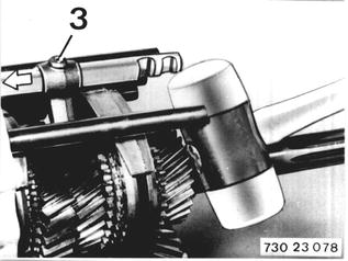 |
Engage 2nr gear. Knock out pin (4), while holding tight. Installation: Replace pin. | 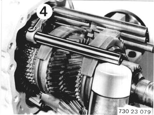 |
Pull off or remove turning lock (5) and operating lever (6). Pull out selector rail (7) forward. Remove 2nd gear again. | 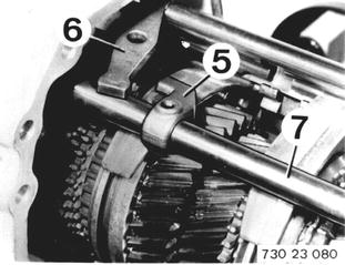 |
Pull out 5th gear selector rod with selector fork and operating sleeve toward rear far enough that lockpin (8) can be knocked out, while holding tight. Important: Loose balls, springs and slides. Installation: Replace lockpin. | 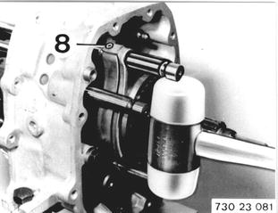 |
Pull off operating sleeve and 5th gear selector fork. Pull out selector rod (9) forward. Important: Loose balls. | 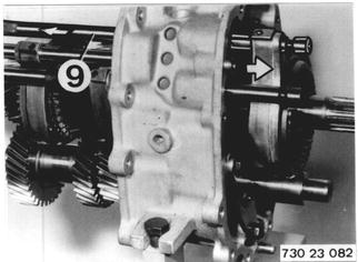 |
Pull guide sleewe and bearing inner race off of output shaft with Special Tools 23 1 420 and 33 1 301. | 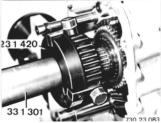 |
Pull off reverse gear and needle bearing. Only for Version with Reverse Gear Synchronization: Remove synchromesh ring. | 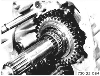 |
Insert 3rd gear. Knock out lockpin (10). Important: Knock lockpin on tooth of 3rd gear until selector rod can be pulled out forward. Remove 3rd/4th gear selector fork. Loose balls! Installation: Replace lockpin. |  |
Pull out output shaft toward rear far enough that bearing inner race can be pulled out with Special Tools 23 1 060 and 33 1 301. | 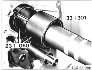 |
 |
|
Pull out input shaft, output shaft and layshaft with 1st/2nd gear selector rod from intermediate case. Important: Loose balls. | 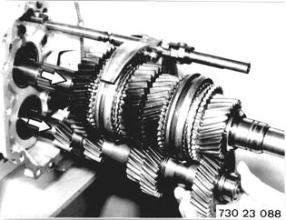 |
Detach holder. | 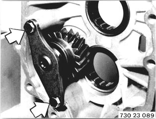 |
Unscrew bolt (11) while holding shaft at front. Installation: Install bolt with Loctite No. 270. Tightening torque¹). Remove washer (12).  ¹) See Specifications ¹) See Specifications
|  |
Knock out reverse gear shaft. Installation: Watch installed position of thrust washer (13). Check needle bearing, replacing if necessary. Check whether all bearings can be reused, replacing if necessary (see 23 21 703).  23 21 703 23 21 703
| 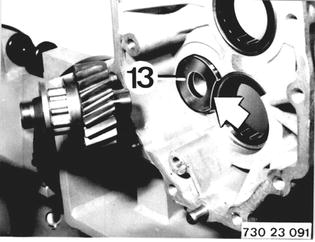 |
Installation: Install and mount reverse gear. Shouldered collar of reverse gear faces holder. | 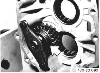 |
Install input shaft, output shaft and layshaft in intermediate case. | 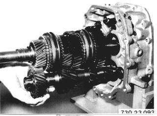 |
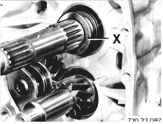
Install shim X. Heat bearing bushing (1) to about 80°C (176°F) and push on output shaft. | 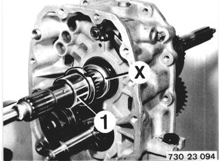 |
Install needle bearing and reverse gear. Version with Reverse Gear Synchronization: Install synchromesh ring. | 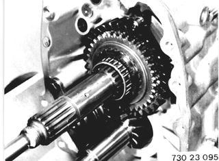 |
Knock out lockpin from 1st/2nd gear selector rod. Installation: Replace lockpin. | 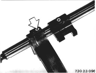 |
Install 1st/2nd gear selectorfork. Push in 1st/2nd gear selector rod against spring. Insert detent balls and push down. Push in selector rod against lock in this position. | 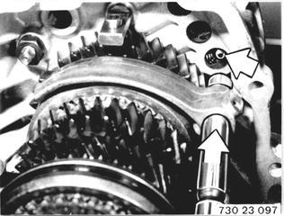 |
Knock in 6 x 32 mm lockpin while holding. | 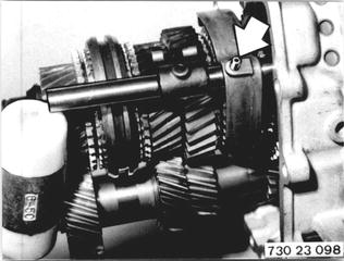 |
Shift Lock Arrangement: 1 Detent ball 2 Spring 3 Locking ball | 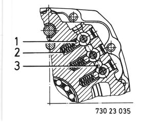 |
Install 3rd/4th gear selector fork. Insert locking ball. Push in selector rod against spring. Insert detent ball and push down. Push in selector rod against lock in this position. Important: When sliding in selector rod opening (1) faces up. | 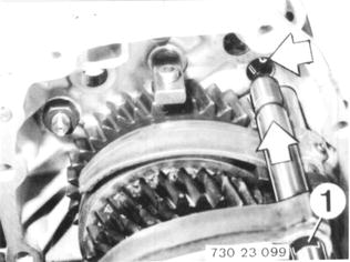 |
Knock in 6 x 26 mm lockpin while holding. | 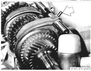 |
Assemble synchronizer. Springs (2), thrust pads (3) and balls (4). Insert all springs, thrust pads and balls. Curved surfaces of thrust pads (3) face operating sleeve. Push in balls far enough that guide sleeve can move into sliding sleeve. | 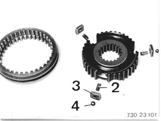 |
Important: Shouldered end of sliding sleeve must be on opposite side of centering pin (5). | 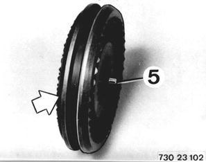 |
Only for Version with Reverse Gear Synchronization: Important: Position sliding sleeve that locking lever (1) aligns with groove (2) in sliding sleeve. | 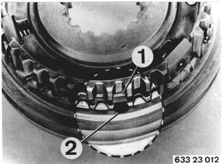 |
Install guide sleeve. Centering pin (5) faces 5th gear. Install 5th/reverse gear selector fork. Insert locking ball. Push in selector rod against spring. Insert detent ball and push down. Push in and turn selector rod that openings (1 and 2) are always opposite the detent ball. |  |
Push in selector rod far enough that 6 x 26 lockpin can be knocked in while holding. Push in selector rod and guide sleeve against lock. | 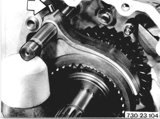 |
Install operating lever (6). Smooth side faces down. Install selector rail (7). Push on turning lock (5). Lock with 6 x 26 mm lockpin. | 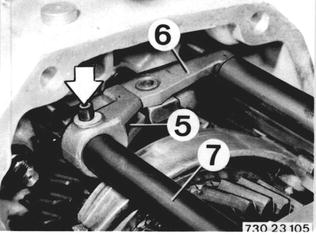 |
Apply Special Tool 23 1 450 in centering pin. Heat bearing bushing to about 80°C (176°F) and push on output shaft. | 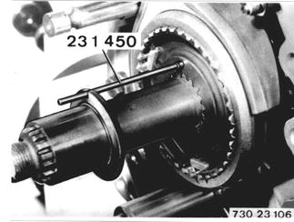 |
Install split needle bearing, synchromesh ring and 5th gear. | 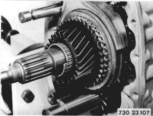 |
Remove transmission from carrier bracket and fit on to press. Oil sliding part on Layschaft. Heat 5th gear wheel to + 150°C uniformly allround. Check with thermocrome-stick. Place 5th gear wheel on layshaft and press on to base with tool 23 1 430. Pressing on force 5 ... 8 t. | 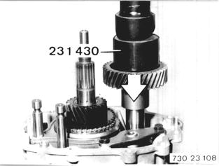 |
Important: Lift and turn 5th gear until teeth mesh. | 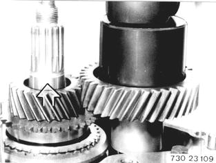 |
Knock bearing inner race on layshaft with Special Tool 23 1 030. Collar of inner race faces gear. | 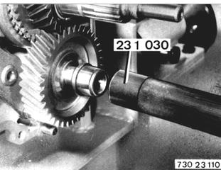 |
Hold ball (2) in position with grease. Push on washer (1). | 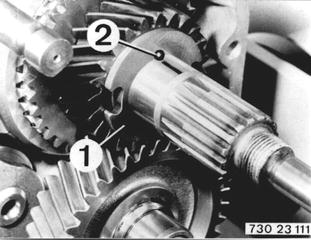 |
Installation: Heat ball bearing inner race to about 80°C (176°F) and push on output shaft. Important: Turning lock! Opening in bearing inner race must engage in ball. Draw reference line (1) to facilitate installation of bearing inner race. | 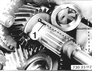 |
Install selector shaft, pushing on selector arm (3) with the long finger facing 3rd/4th gear selector rod. Important: Lock on selector shaft faces selector rail (4). Knock in lockpin 6 x 32 mm, while holding. | 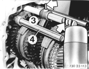 |
Hold 4 rollers on selector shaft with grease. | 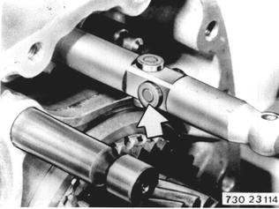 |
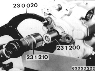
Vehicles after change point in 1982 REMOVING AND INSTALLING INPUT AND OUTPUT SHAFT ASSEMBLY - TRANSMISSION REMOVED - Detach transmission case front section 23 11 013. Remove lockplate. Apply Special Tool 23 1 200. Hold output flange with Special Tool 23 0 020. Unscrew collar nut with Special Tool 23 1 210.  23 11 013 23 11 013
|  |
Pull off output flange with Special Tool 33 1 150. | 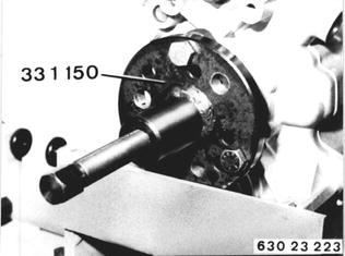 |
Unscrew bolt (1). Remove holder (2). Unscrew bolt (3). | 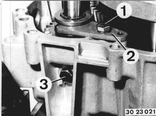 |
Remove shaft with reverse gear and needle bearing. | 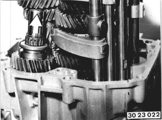 |
Pull out pin (4) for operating lever (5). Pull out selector rail (6). Remove operating lever (5). Installation: Install lever that notch on operating lever faces up and toward selector rail. |  |
Engage 4th gear. Knock out pin (7) (counterhold). Important! Only knock out pin (7) far enough that the selector shaft can be pulled out toward rear. | 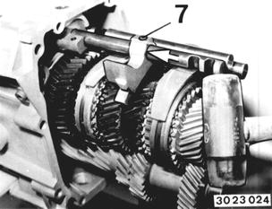 |
This will also pull out radial oil seal (8). Important! Rollers on selector shaft. Installation: Replace radial oil seal. Remove selector arm. | 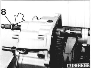 |
Detach end cap. Installation: Install end cap with Loctite No. 573. Sealing surface must be thoroughly cleaned and dried of oil. Remove end cover (9). Installation: Replace end cover. | 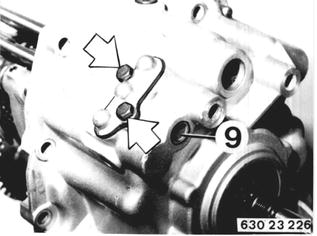 |
Remove 3 springs and 3 balls. Note: Length of springs differs (see installation). | 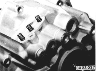 |
Drive out pin (10) in 3rd/4th gear selector fork. Installation: Replace pin. | 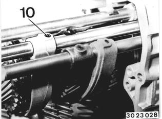 |
Knock out 3rd/4th gear selector rod forward. Important! Lockpin (11) in selector rod. | 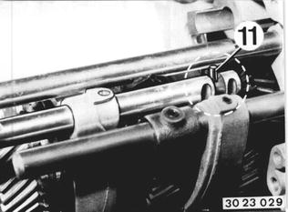 |
Engage 2nd and reverse gears by pushing 1st/2nd and 5th/reverse gear selector rods forward. | 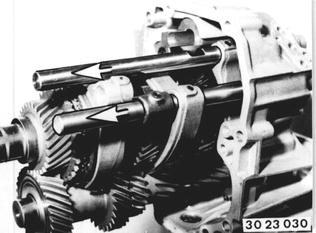 |
Press input shaft, output shaft and layshaft out of rear case section with Special Tool 23 1 050. Important! To avoid sealing surface damage, use a piece of wood, aluminum or similar material between claws and sealing surface. | 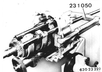 |
Important! Be careful not to clamp selector rods and layshaft while pressing out parts. The layshaft must not tilt off during this step. Installation: Check condition of all bearings, replacing if necessary. | 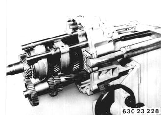 |
Installing: Install 3rd/4th gear selctor fork and 1st/2nd as well as 5th/reverse gear selector rods with selector forks. Only 260/5: Check thrust washer (1). | 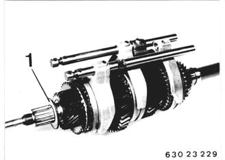 |
Remove all detent and locking balls in rear case section. Install roller bearings with large diameter end facing out. Lubricate lockpin and locking lever with oil. Transmission 260/6: The output flange radial oil seal and ball bearing inner race have to be removed prior to installing the input shaft and output shaft. | 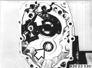 |
Heat grooved ball bearing inner race in rear case section to about 80°C /175°F) with a hot air blower. Second and reverse gears are engaged. Insert input shaft, output shaft and layshaft in case rear section. Align selector rods. | 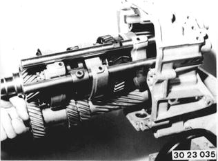 |
Pull input shaft, output shaft and layshaft into rear case section with Special Tools 23 1 300 and 23 2 150. Important! Make sure selector rods and layshaft are not clamped while pulling in parts. | 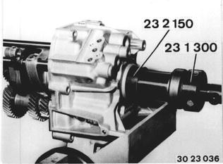 |
Transmission 260/6: Place input shaft and output shaft with 3rd/4th gear selector forks and 5th/reverse gear plus 1st/2nd gear selector rods as well as layshaft in the rear case section. Heat bearing inner race (1) to about 80°C (175°F) with a hot air blower and slide on to the output shaft, pressing on with Special Tool 23 1 160 if necessary. | 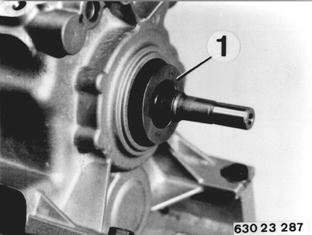 |
Transmission 260/6: Drive in radial oil seal flush with Special Tool 23 1 370. Lubricate sealing lip with oil. | 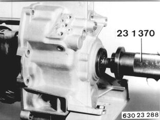 |
Move selector rods to neutral position. Slide 3rd/4th gear selector rod through selector forks. Install lockpin (1) in selector rod with grease. Push in selector rod up to bore. Opening in selector rod faces up. | 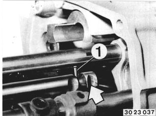 |
Install two detent balls with grease. Push in 3rd/4th gear selector rod against lock. | 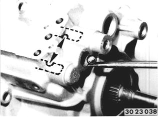 |
Arrest Assembly: 1 End cap 2 Spring 3 Locking ball 4 Detent ball 5 Lockpin 6 Selector arm 7 Lockpin 8 Spring 9 Locking lever 10 Spring | 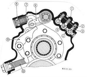 |
Drive 6 x 26 mm pin into 3rd/4th gear selector fork (counterhold). | 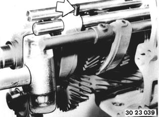 |
Install 3 locking balls and 3 springs. Important! Version with Different Length Springs: Install the shorter spring (1) with a relaxed length (A) of 15.9 mm (0.626´´) for the 5th/ reverse gear selector rod. | 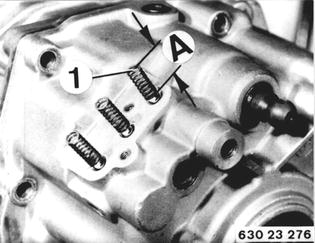 |
Install end cap after coating with Loctite No. 573. Install end cover with Loctite No. 573. | 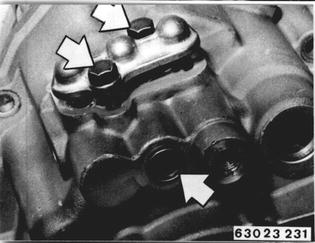 |
Drive pin out of selector arm. | 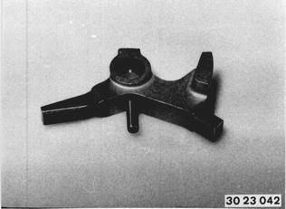 |
Hold four rollers in position with grease. Slide in selector shaft and install selector arm (1) at same time. Important! Opening in selector shaft faces out. | 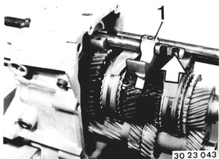 |
Drive in 6 x 26 mm pin (counterhold). | 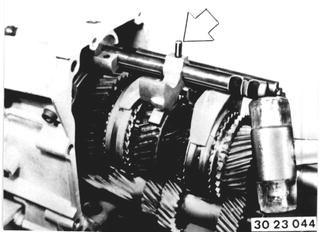 |
Lubricate sealing lips of radial oil seal with oil. Drive in radial oil seal with Special Tool 23 1 240. | 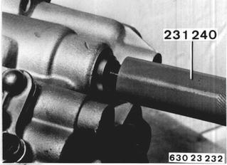 |
Install selector rail. Groove (1) in selector rail faces up. Install operating lever (5) with notch facing up and toward selector rail. Install pin (4). | 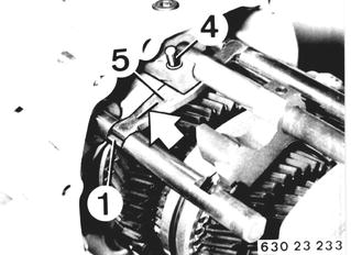 |
Coat case rear section in area of reverse gear shaft with Loctite No. 573. Surface must be thoroughly cleaned and dried of oil. | 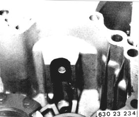 |
Install shaft with needle bearing and reverse gear. | 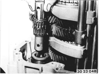 |
Mount shaft with bolt (3). Install bolt with Loctite No. 270. | 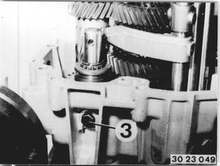 |
Insert holder (2), press out and secure in this position. | 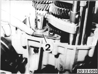 |
Install output flange. Install collar nut with Loctite No. 270. Apply Special Tool 23 1 200. Hold output flange with Special Tool 23 0 020. Tighten collar nut with Special Tool 23 1 210. Tightening torque*.  * See Specifications * See Specifications
|  |
Install and lock lockplate. | 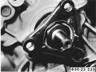 |
BMW 628csi - M635csi (M6)»23 - Transmission-manual»23 21 503 - Input and output shafts - removing and installing