REPLACING OUTPUT SHAFT - OUTPUT SHAFT REMOVED - Pull off input shaft (1), synchromesh ring (2) and needle bearing (3). | 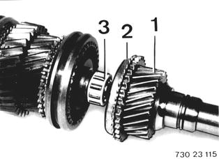 |
Lift off circlip (4). Remove washer (5). Installation: Take up excessive play between circlip and guide sleeve. Max. axial play: 0.09 mm (0.0035´´). | 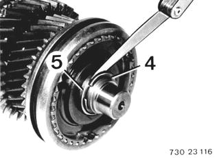 |
Pull off guide sleeve, synchromesh ring, 3rd gear and needle bearing. | 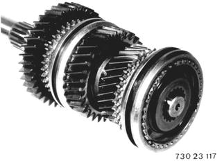 |
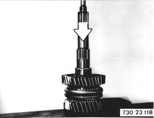
Press 2nd gear, needle bearing, synchromesh ring, guide sleeve, synchromesh ring, 1st gear, needle bearing with bearing bushing and bearing inner race off of output shaft. Check condition of all needle bearings, replacing if necessary. Check synchromesh rings (see 23 23 505).  23 23 505 23 23 505
|  |
Install needle bearing, 2nd gear, synchromesh ring and guide sleeve with offset groove facing 1st gear. Place bearing bushing and needle bearing in 1st gear. Install synchromesh ring. Push in output shaft. Important: Guide synchromesh ring with tabs into sliding sleeve. | 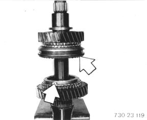 |
Push on bearing inner race (7) with Special Tool 23 1 440. | 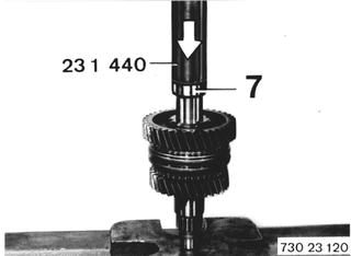 |
Determine thickness of shim X. Measure distance (A) from collar of output shaft to bearing inner race. | 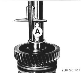 |
Place reverse gear bearing bushing in guide sleeve. Measure distance (B) from collar of guide sleeve to bearing bushing. Example: A 52.2 mm (2.055´´) - B 52.0 mm (2.047´´) --------------------------------- X 0.2 mm (0.008´´) shim thickness | 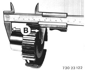 |
LAYOUT DRAWINGS OF GEARS AND BEARINGS 1 Ball bearing 2 Input shaft and 4th gear 3 Turning lock 4 Needle bearing 5 Synchromesh ring 6 Circlip 7 Washer 8 Thrust pad 9 Ball 10 Spring 11 Guide sleeve 12 Sliding sleeve 13 3rd gear 14 Needle bearing 15 Bearing bushing 16 Output shaft 17 Ball 18 2nd gear 19 1st gear 20 Bearing race 21 Roller bearing 22 Shim X 23 Reverse gear 24 Circlip 25 Bearing bushing 26 Split needle bearing 27 5th gear 28 Washer 29 Ball bearing 30 Washer 31 Speedometer gear 32 Radial oil seal 33 Output flange 34 Collar nut 35 Lockplate 36 Roller bearing 37 4th gear 38 Circlip 39 3rd gear 40 Layshaft 41 Roller bearing 42 5th gear 43 Roller bearing 44 Bolt 45 Washer 46 Washer 47 Thrust washer 48 Needle bearing 49 Reverse gear 50 Shaft 51 Shaft holder | 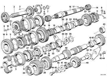 |
Vehicles after change point in 1982 REPLACING OUTPUT SHAFT - Output Shaft Removed - Pull off input shaft (1), synchromesh ring (2) and needle bearing (3). Note: It is recommended to mark synchromesh rings for a pertinent gear wheel when disassembling the output shaft, in order to avoid mixing up synchromesh rings. | 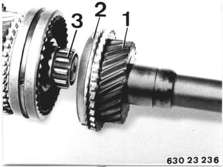 |
Pull off thrust washer (4), 5th gear (5), synchromesh ring (6) and needle bearing (7). | 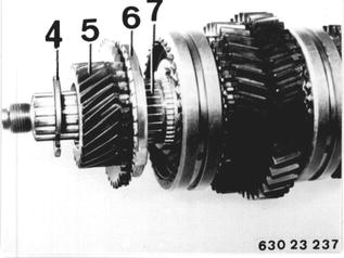 |
Transmission 260/6: Pull off bearing inner racer (1) with Kukko 00 7 500 from output shaft. | 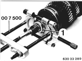 |
Transmissin 260/6: Pull off 5th gear and synchromesh ring. Take off thrust washer (2) and ball (3). Pull off needle bearing. | 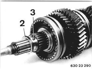 |
Lift out circlip (8). Take off spacer (9). Installation: Always replace circlip. | 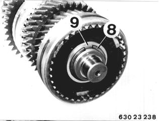 |
Installation: Adjust play between circlip and guide sleeve to 0 ... 0.09 mm (0 to 0.0035´´). | 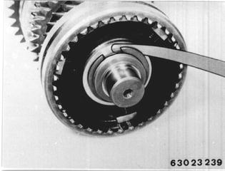 |
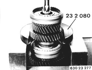
Press 2nd gear, bearing sleeve, 3rd gear, synchromesh ring and guide sleeve off of output shaft with Special Tool 23 2 080. Pressing-off force*.  * See Specifications * See Specifications
|  |
Transmission 260/6: Note thrust washer (2) and ball (3) between 2nd and 3rd gear wheels. | 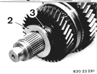 |
Important! Circlip (10) has to be removed prior to pressing off the 1st gear wheel. Installation: Always replace circlip. | 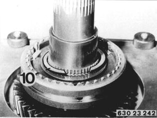 |
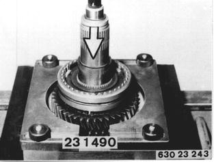
Press off 1st gear wheel with guide and operating sleeves with Special Tool 23 1 490. Take off needle bearing. Pressing-off force*.  * See Specifications * See Specifications
|  |
Important! Circlip (11) has to be removed prior to pressing off the reverse gear wheel. Installation: Always replace circlip. | 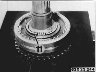 |
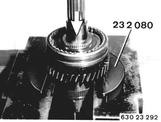
Press off guide sleeve, operating sleeve and reverse gear wheel with Special Tool 23 2 080, the bottom end of which faces the gear wheel. Take off needle bearing. Pressing-off force*.  * See Specifications * See Specifications
|  |
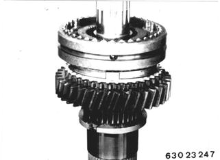
Assembling: Note: Check synchromesh rings for wear (see 23 23 505) prior to assembling. Install needle bearing, reverse gear and synchromesh ring. Install guide and operating sleeves on splines of output shaft. Transmission 260/6 and 260/5**: Stepped end of sliding sleeve faces reverse gear or, in case of version with 1 groove, 5th gear.  23 23 505 23 23 505 ** Since 5.85 ** Since 5.85
|  |
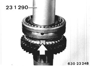
Press on guide sleeve to fit tight with Special Tool 23 1 290. Pressing-on force*. Important! Make sure that tabs on synchromesh ring are aligned with openings in guide sleeve while pressing on.  * See Specifications * See Specifications
|  |
Move operating sleeve in direction of reverse gear wheel. Adjust guide sleeve to be without play with circlip (11). Circlips are available from Parts in different thicknesses from 1.7 to 2.0 mm (0.067 to 0.079´´). Install circlip (11). | 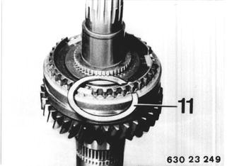 |
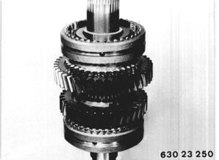
Install needle bearing, 1st gear wheel and synchromesh ring. Install guide and operating sleeves on splines of output shaft. Transmission 260/6 and 260/5**: Stepped end of operating sleeve faces 1st gear wheel. Version with Two Grooves: The grooves must face the 2nd gear wheel.  ** Since 5.85 ** Since 5.85
|  |
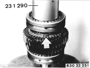
Press on guide sleeve to fit tight with Special Tool 23 1 290. Pressing-on force*. Important! Make sure that tabs on synchromesh ring are aligned with openings in guide sleeve while pressing on.  * See Specifications * See Specifications
|  |
Move operating sleeve in direction of the 1st gear wheel. Adjust guide sleeve to remove play. Circlips are available from Parts in different thicknesses from 1.7 to 2.0 mm (0.067 to 0.079´´). Install circlip (10). | 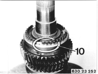 |
Install needle bearing, synchromesh ring and 2nd gear wheel. Important! The collar for the bearing sleeve must protrude slightly on the output shaft. If applicable, check seating of circlip (10). | 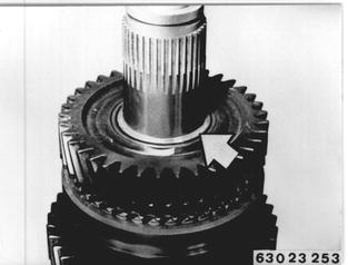 |
Heat bearing sleeve to about 80°C (175°F) with a hot air blower and install on output shaft. | 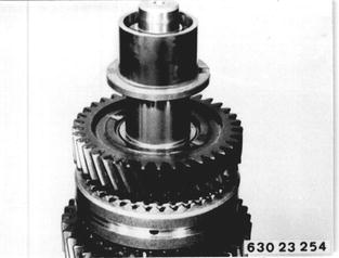 |
Transmission 260/6: Install ball (3) and thrust washer (2) with opening facing ball (3). | 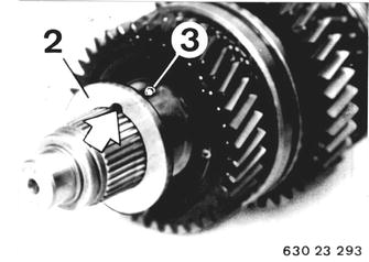 |
Transmission 260/6: Heat bearing sleeve (4) without collar to about 80°C (175°F) with a hot air blower and install on output shaft. | 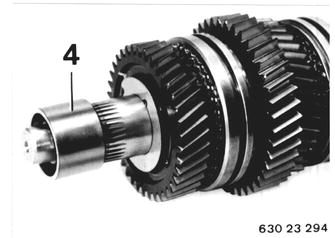 |
Install needle bearing, 3rd gear wheel and synchromesh ring. Install guide and operating sleeves on splines with the long collar facing the 3rd gear wheel. Version with Three Grooves: The grooves must face the 4th gear wheel. | 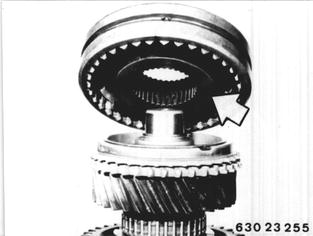 |
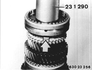
Press on guide sleeve to fit tight with Special Tool 23 1 290. Important! Make sure that tabs on synchromesh ring are aligned with openings in the guide sleeve while pressing on. Install spacer and circlip. Pressing-on force*.  * See Specifications * See Specifications
|  |
Pull off thrust washer (4), 5th gear wheel (5), synchromesh ring (6) and needle bearing (7). |  |
Transmission 260/6: Slide needle bearing on to output shaft. Install ball (3). Install thrust washer (2) with opening facing the ball. Install synchromesh ring and 5th gear wheel. | 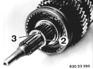 |
Transmission 260/6: Heat ball bearing inner race to about 80°C (175°F) with a hot air blower and install on output shaft. Important! Opening in bearing inner race must take the ball (turning lock). | 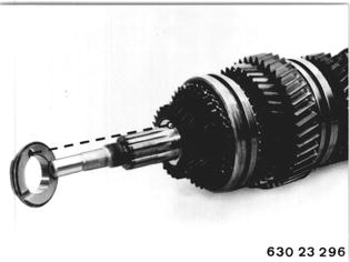 |
Transmission 260/5: Important! There are different sliding sleeves, synchromesh rings and gear wheels since 5.85. Check installed position of sliding sleeves and synchromesh rings. Sliding sleeves have asymmetric splines. Stepped end of sliding sleeve (1) without groove faces 1st gear wheel or, version with 2 grooves, faces 2nd gear wheel. Stepped end of sliding sleeve (3) with 2 grooves faces 3rd gear wheel or, version with 3 grooves, faces 4th gear wheel. Stepped end of sliding sleeve (5) with 1 groove faces reverse gear wheel or, version with 1 groove, faces 5th gear wheel. |  |
Identification of Synchromesh Rings: To avoid mixing up synchromesh rings among each other, it is important to note the drawing number and tooth width. Synchromesh ring (1) for 1st/reverse gears has drawing no. 001.8.0241.00 and narrow teeth. Synchromesh ring (2) for 2nd, 3rd, 4th and 5th gears has drawing no. 011.8.0161.00 and wide teeth. | 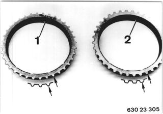 |
Transmission 260/6: Installed Position of Sliding Sleeves/Gear Wheels: 1st/2nd gear sliding sleeve (1) - installed with stepped end facing 1st gear wheel or, for version with 2 grooves, facing 2nd gear wheel. 5th/reverse gear sliding sleeve (5) - installed with stepped end facing reverse gear wheel or, for version with 1 groove, facing 5th gear wheel. | 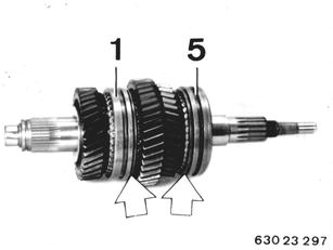 |
Transmission 260/6: Identification of Synchromesh Rings: To avoid mixing up synchromesh rings for 1st/ 2nd and 5th/reverse gears, they must be checked for codes and tooth width. Synchromesh ring for 1st/reverse gears has drawing no. 011.8.0241.00 and narrow teeth. Synchromesh ring for 2nd/5th gears has drawing no. 011.8.0161.00 and wide teeth. | 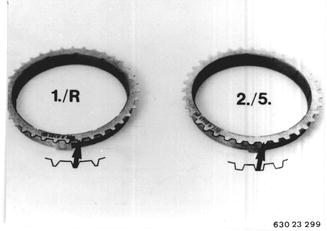 |
Gear Set and Bearing Layout Drawing 1 Circlip 2 Spacer 3 Spacer 4 Bearing 5 Input shaft with 4th gear 6 Synchromesh ring 7 Needle bearing 8 Circlip 9 Spacer 10 Drive dog 11 Ball 12 Spring 13 Guide sleeve 14 Operating sleeve 15 3rd gear 16 Needle bearing 17 Spacer 18 Needle bearing 19 2nd gear 20 Synchromesh ring 21 Circlip 22 Guide sleeve 23 Synchromesh ring 24 Operating sleeve 25 1st gear 26 Needle bearing 27 Output shaft 28 Reverse gear 29 Synchromesh ring 30 Guide sleeve 31 Circlip 32 Needle bearing 33 5th gear 34 Bearing 35 Spacer 36 Spacer 37 Speedometer drive gear 38 Output flange 39 Collar nut 40 Lockplate 41 Circlip 42 Spacer 43 Bearing 44 Layshaft 45 Bearing |  |