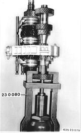
Vehicles after change point in 1982 REMOVING AND INSTALLING INPUT AND OUTPUT SHAFT ASSEMBLY - Front and Rear Transmission Case Sections Removed - Clamp Special Tool 23 0 080 in a vise. Take intermediate case with gear wheel set off of Special Tool 23 0 030 and mount it on Special Tool 23 0 080. Pull off the 5th gear wheel. Pulling-off force*.  * See Specifications * See Specifications
|  |
Important! Always make sure that there is play (S) between the 3rd gear wheel and layshaft while pulling off the 5th gear wheel, to avoid damaging the 3rd gear wheel: If necessary, push up the output shaft. | 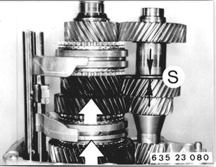 |
Mount intermediate case with gear wheel set on Special Tool 23 0 030 again. Pull bearing inner race off of the output shaft with Special Tools 23 1 100 and 00 7 500. The pulling hooks must be modified to fit in the slots. | 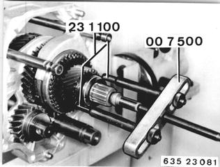 |
Take off washer (1) and ball (2). | 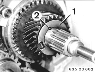 |
Pull off 5th gear wheel with synchromesh ring and split needle bearing. | 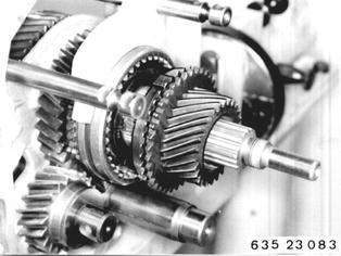 |
Lift out circlip (3). Installation: Replace circlip. | 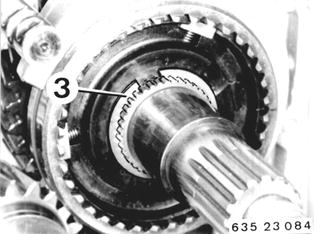 |
Pull off reverse gear wheel with guide nut and selector rod with Special Tool 23 1 050. | 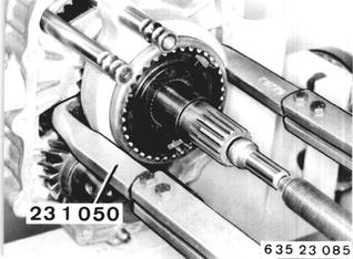 |
Take guide sleeve with selector fork and selector rod, synchromesh ring, reverse gear wheel and needle bearing off of the output shaft. Important! - Installation: The stepped end of the sliding sleeve faces the reverse gear wheel. | 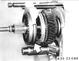 |
Pull input shaft, output shaft with 1st/2nd gear selector rod, 3rd/4th gear selector fork and layshaft out of the intermediate case. | 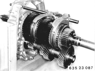 |
Take selector rod with 1st/2nd gear selector fork and 3rd/4th gear selector fork off of the gear wheel set. | 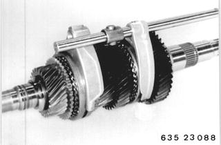 |
Installation: Install input shaft, output shaft with 1st/2nd gear selector rod and layshaft in the intermediate case. | 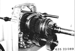 |
Install needle bearing, reverse gear wheel and synchromesh ring on the output shaft. | 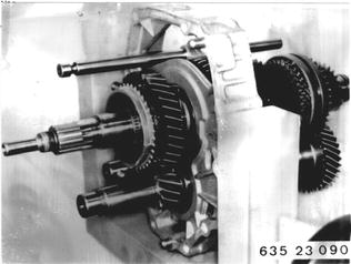 |
Install guide sleeve with sliding sleeve and selector rod with 5th/reverse gear selector fork on the output shaft. Important! Stepped end of sliding sleeve faces the reverse gear wheel. | 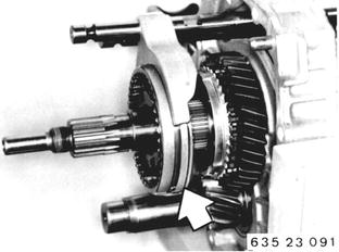 |
Drive on guide sleeve with light knocks from Special Tool 23 1 290. Important! The tabs on the synchromesh ring must be aligned with openings in the guide sleeve. | 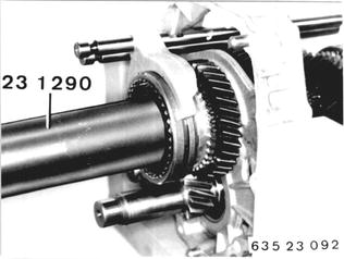 |
Shift the sliding sleeve in direction of the reverse gear wheel. Remove all play on guide sleeve with circlip (3). Circlips are available from Parts in different thicknesses from 1.7 to 2.0 mm (0.067 to 0.079´´). Install circlip (3). | 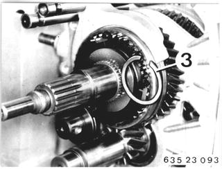 |
Install the synchromesh ring and 5th gear wheel. | 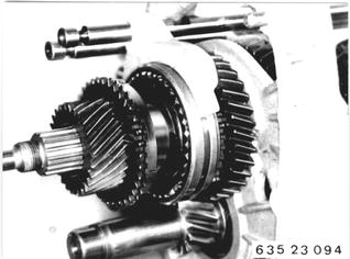 |
Take intermediate case with gear wheel set off of Special Tool 23 0 030 and mount it on a press. Lubricate pressing surface of layshaft with oil. Heat 5th gear wheel uniformly to 150°C (300°F), checking temperature with a thermochrome pencil. Mount the 5th gear wheel on the layshaft and press it on to fit tight with Special Tool 23 1 430. Pressing-on force*.  * See Specifications * See Specifications
| 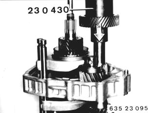 |
Important! Lift and turn the 5th gear wheel until the teeth mesh. | 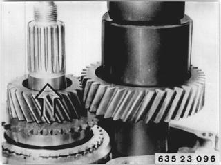 |
Install split needle bearing. Install ball (2) with grease. Slide on washer (1). |  |
Installation: Heat the ball bearing inner race to about 80°C (175°F) with a hot air blower and slide it onto the output shaft. Important! Turning lock - opening in bearing inner race must engage on ball. Draw line (1) to make installation of the bearing race easier. | 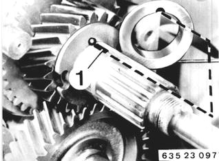 |
Install the 3rd/4th gear selector fork. | 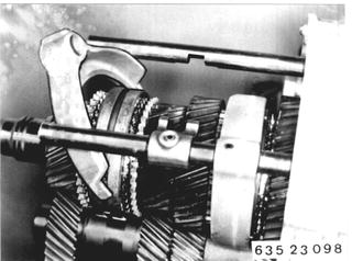 |
BMW 628csi - M635csi (M6)»23 - Transmission-manual»23 21 501 - Input and output shaft assembly - remove and install