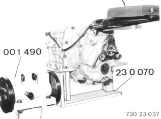
REMOVING AND INSTALLING/SEALING TRANSMISSION CASE FRONT SECTION Remove transmission 23 00 020. Detach rubber mount. Mount transmission on Special Tools 23 0 070 and 00 1 490. Drain oil  23 00 020 23 00 020
|  |
Pull off wires on backup light switch. Detach wire harness at suspension. | 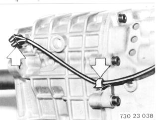 |
Detach console. | 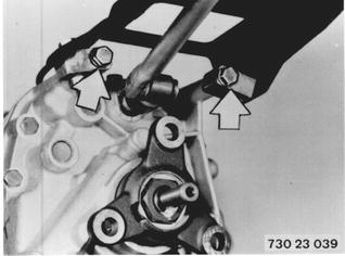 |
Engage 3rd gear. Push back sleeve (1). Knock out cylindrical pin (2). Pull off selector rod. | 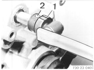 |
Unscrew backup light switch. Detach guide flange. Important: Watch length of bolts. Bolts (1 ... 3) = 8 x 30 mm Bolts (4 ... 7) = 8 x 22 mm Install bolts with Loctite No. 573. | 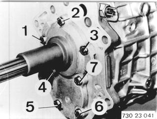 |
Remove guide flange. Important: Coat sealing surfaces with Loctite No. 270. Sealing surfaces must be absolutely clean and free of oil. | 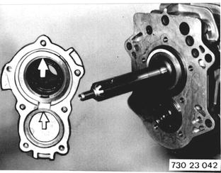 |
Remove circlip (1). Remove slotted washer (2). Installation: Install slotted washer that slot faces circlip. | 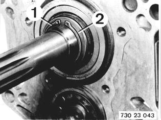 |
Remove circlip (3). Remove washer (4). | 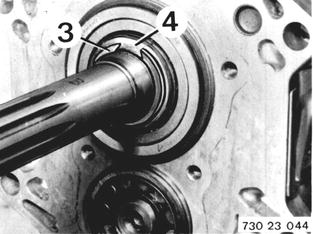 |
Remove cover (5). Remove spring (6) and lockpin (7). Installation: Watch installed position. | 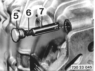 |
Knock out cylindrical pin. Unscrew bolts. | 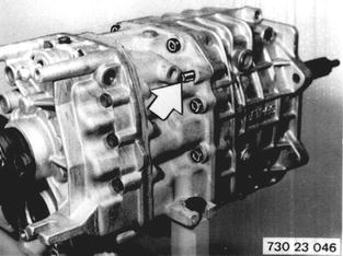 |
Pull off transmission case front section with Special Tools 23 1 170 and 33 1 301. | 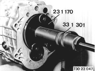 |
Coat sealing surfaces with Loctite No. 573. Sealing surfaces must be absolutely clean and free of oil. Attach transmission case front section. | 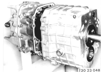 |
Install lockpin and backup light switch. Arrangement of Lockpin. | 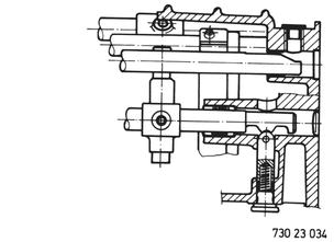 |
Heat ball bearing inner race (8) to about 80°C (176°F) and push on input shaft. Pull out input shaft for this job. | 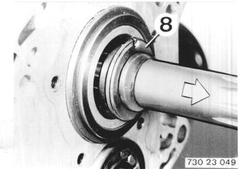 |
Take up play between washer (4) and circlip (3). Circlips (3) are available in different thicknesses from Parts. Install slotted washer and circlip. | 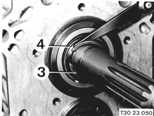 |
Take up play of grooved ball bearings on input shaft and layshaft to guide flange. Distance A = 7.8 mm (0.307´´) - input shaft Distance B = 4.3 mm (0.169´´) - layshaft | 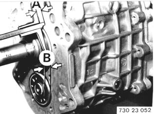 |
Measure distances C and D. Distance C = 8.1 mm (0.319´´) - input shaft Distance D = 4.8 mm (0.189´´) - layshaft Input shaft: C 8.1 mm (0.319´´) - A 7.8 mm (0.307´´) ------------------------------- 0.3 mm (0.012´´) shim thickness | 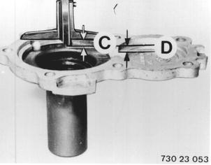 |
Layshaft: D 4.8 mm (0.189´´] - B 4.3 mm (0.169´´) ------------------------------- 0.5 mm (0.020´´) - 0.1 ... 0.2 mm (0.004 ... 0.008´´) play ---------------------------------------------------- 0.3 ... 0.4 mm (0.012 ... 0.016´´) shim Hold shims in position with grease. Attach guide flange. | 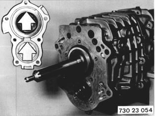 |
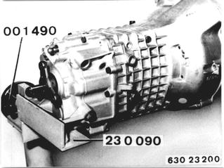
Vehicles after change point in 1982 REMOVING AND INSTALLING/SEALING TRANSMISSION CASE FRONT SECTION Remove transmission 23 00 022. Mount Special Tool 23 0 090 on Special Tool 00 1 490. Mount transmission on special tool assembly. Drain oil.  23 00 022 23 00 022
|  |
General Information: A stronger five speed overdrive manual transmission, Type 260/6, is installed since 9.85 in cars with a 3.2 or 3.4 liter M 30 engine. It can be identified on the additional cooling ribs on the bottom of the case. The 260/6 overdrive transmission has been included in the following description for the formerly installed Type 260/5 overdrive transmission. | 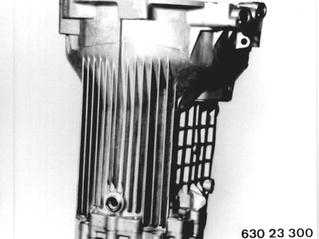 |
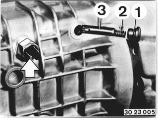
Remove guide sleeve 23 11 623. Unscrew backup light switch. Remove cap (1). Pull out spring (2) and lockpin (3). Check installed position!  23 11 623 23 11 623
|  |
Remove snap ring (4). Remove washer (5). Installation: Always replace snap ring. | 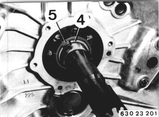 |
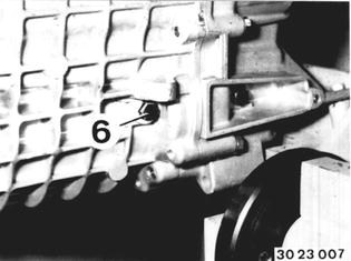
Unscrew bolt (6). Installation: Install bolt with Loctite No. 270. Tightening torque*.  * See Specifications * See Specifications
|  |
Drive out cylindrical pins. Unscrew bolts. Installation: Check length of bolts. Bolt (1) = 8 x 60 mm | 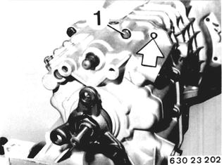 |
Pull off front case section with Special Tools 23 1 460 and 33 1 301. | 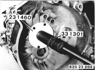 |
Install roller bearing on layshaft that small diameter end faces up. Note: Coat rollers with grease and press in, in order to avoid clamping of rollers when mounting the case front section. | 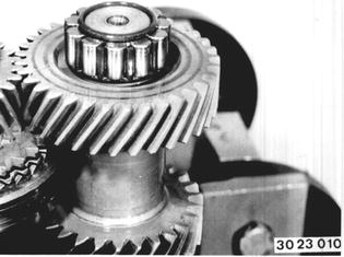 |
Coat case front section in area of reverse gear shaft with Loctite No. 573. Surface must be thoroughly cleaned and dried of oil. | 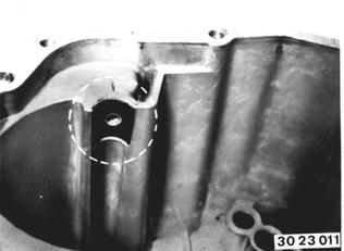 |
Remove grooved ball bearing for input shaft. Important! Inner race of grooved ball bearing has a protrusion. Protrusion faces gear shaft. | 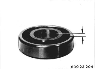 |
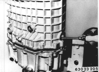
Unscrew oil drain plug. Coat sealing surface with Loctite No. 573. Sealing surface must be thoroughly cleaned and dried of oil. Mount front case section. Align layshaft through bore for oil drain plug that roller bearing of layshaft slides into bearing shell. Bolt front case section. Tightening torque*. Install lockpin and reverse gear switch.  * See Specifications * See Specifications
|  |
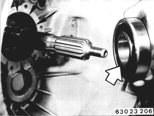
Heat* bearing inner race and front case section in area of grooved ball bearing with a hot air blower. Push on grooved ball bearing as far as possible. Inner race protrusion faces gear set.  * See Specifications * See Specifications
|  |
Press grooved ball bearing on to input shaft and into front case section with Special Tools 23 1 007, 23 1 000 and 23 1 006. Important! Insert Special Tools 23 1 006 that flat sides face input shaft. | 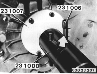 |
Keep driving on grooved ball bearing simultaneously with light hammer knocks. | 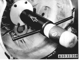 |
Transmission 260/6: The front case section cannot be pressed on, because of the uniform thickness of the input shaft. A double bearing is installed in the front case section. Heat bearing inner race to about 80°C (175°F) with a hot air blower. Important! Protect plastic cage against heat. Mount front case section, pulling out the input shaft for this purpose. Bolt front case section. Tightening torque*.  * See Specifications * See Specifications
| 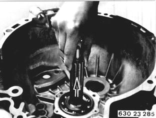 |
Install spacer and circlip. Adjust plat between bearing inner race and circlip to 0 ... 0.09 mm (0 to 0.0035´´). | 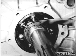 |
BMW 628csi - M635csi (M6)»23 - Transmission-manual»23 11 013 - Transmission case front section - removing and installing/sealing