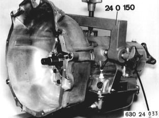
Vehicles before change point in 1982 DISASSEMBLING/ASSEMBLING TRANSMISSION Remove transmission 24 00 020. Remove torque converter 24 40 000. Secure transmission on Special Tool 24 0 150 in conjunction with an assembly stand. Important: Only tighten holding bolts slightly to prevent damage to transmission case.  24 00 020 24 00 020 24 40 000 24 40 000
|  |
A) Disassembling: Detach oil pan. | 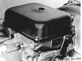 |
Remove valve body. Important: Watch metal supports (1). Version with Torx Bolts: Unsrew Torx bolts with Special Tool 00 2 100. | 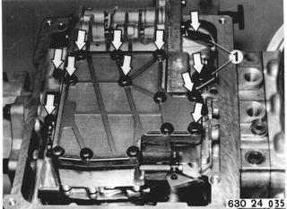 |
Remove circlips. Take out springs (2 ... 5). | 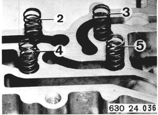 |
Pull out sealing sleeves with Special Tool 24 2 050. | 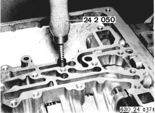 |
Install Special Tool 23 1 200. Hold output flange with Special Tool 23 1 150. Unscrew collar nut with Special Tool 23 1 210. Pull off output flange. | 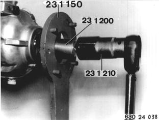 |
Detach transmission extension. | 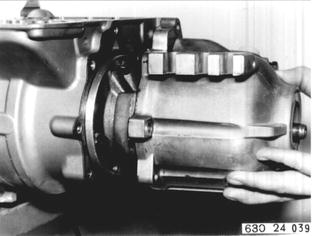 |
Unscrew nut (6) and loosen stud (7) by about 3 turns. Pull off governor. | 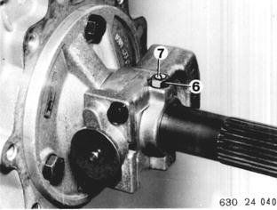 |
Remove converter bell housing with intermediate plate. Important: Thrust washer (8), needle bearing (9) and angled disc (10). | 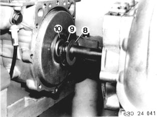 |
Remove input shaft with clutch A. | 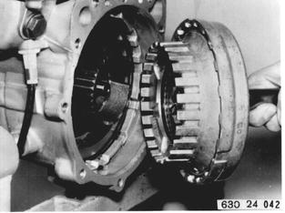 |
Remove plate carrier (11) for clutch A with plastic thrust washer (12) and metal thrust washer (13). | 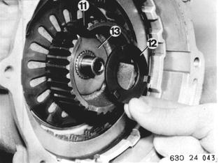 |
Remove snap ring (14). When removing clutch B support disc (15) and seal (16) will also be pulled out. | 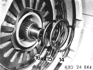 |
Pull out clutch B with two locally manufactured hooks. | 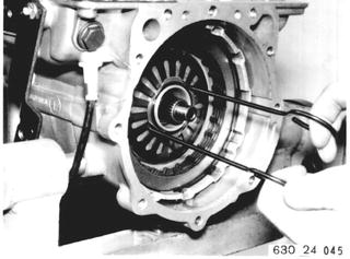 |
Sketch for Local Manufacture: Dimensions in mm. | 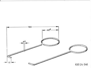 |
Remove snap ring (18). | 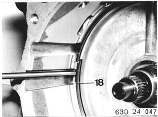 |
Pull out complete assembly. Centering plates (1), clutches C´, C and D (2), set of planet gears with output shaft (3). | 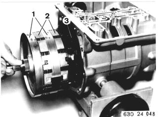 |
Important: Thrust washer (19), needle bearing (20) and angled disc (21). | 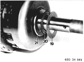 |
Pull centering plate (1), clutch assembly (2) with clutches C´, C and D off of output shaft (3). | 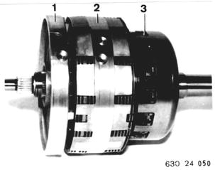 |
Remove set of planet gears with sun gear shaft. Important: Needle bearing (22) and thrust washer (23). | 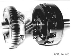 |
B) Assembling Detach governor flange. Replace gasket (1). | 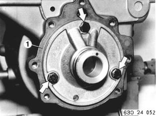 |
Use grease to paste angled disc (2) with the angled side on the output shaft. Install needle bearing and thrust washer on output shaft. | 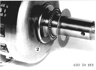 |
Important: Keys (3 and 4) must be in center of cylinder groove. Parking lock must not be engaged. Guide entire output assembly into transmission case, that the 4 oil bores in the output assembly are aligned with the bores in the bottom of the transmission case. | 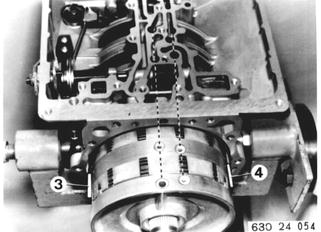 |
Install snap ring (5). | 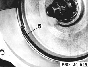 |
Install clutch B. |  |
Insert seal (6) and press in with support disc (7) against stop. Install snap ring (8). | 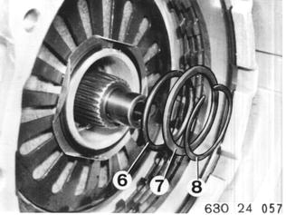 |
Install lubricated plastic thrust washer that the tabs engage in openings of cylinder A. | 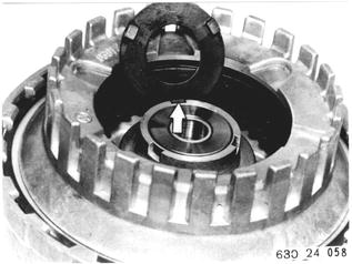 |
Stick metal thrust washer in plate carrier with grease. | 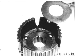 |
Install plate carrier (9) in clutch A by turning back and forth slightly. Install clutch A in transmission case. | 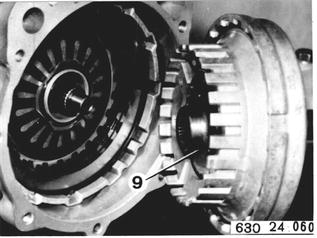 |
Install angled disc (10) on input shaft with collar facing needle bearing (11). | 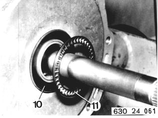 |
Stick thrust washer (12) and gasket (13) on converter bell housing. Slide converter bell housing on input shaft and secure. | 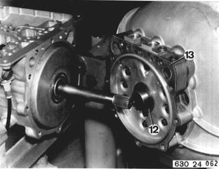 |
Check input shaft axial play. Specification: 0.3 to 1.5 mm (0.012 to 0.059´´) | 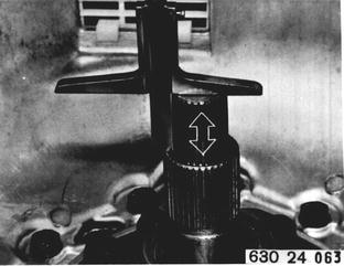 |
Compress piston rings slighty and slide governor on governor flange. Unscrew stud to facilitate finding depression in output shaft. Secure governor in depression of output shaft with stud and lock by counterpunching. | 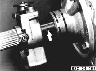 |
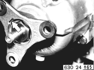
Lubricate sealing lip of radial oil seal with ATF. Attach transmission and output flange. Install collar nut¹) with Curil K 2 or Loctite 572. Place lockplate on nut and lock it in groove of output flange.  ¹) See Specifications for tightening torque ¹) See Specifications for tightening torque
|  |
Use suitable mandrel to drive in 4 sealing sleeves against stop. | 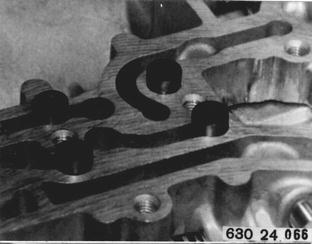 |
Install and secure springs. Both short springs (1 and 2) are on selector lever side. | 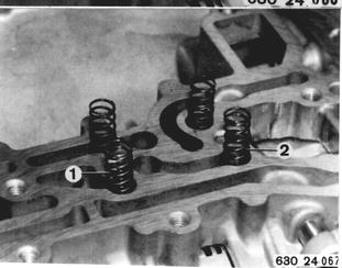 |
Install valve body that clamp on selector sliding valve can be engaged in opening of pawl. This requires tightening transmission cable slightly, so that accelerator cam can´t interfere with throttle pressure valve. | 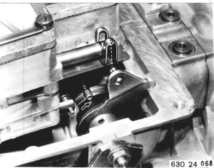 |
Tighten valve body bolts finger tight. Only When Support Plates are Available: Install with support plates (3). | 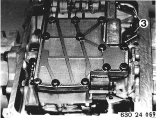 |
Align valve body with Special Tool 24 3 050. If this tool is not available, check that distance from valve body to pin in throttle pressure piston is 11.5 mm (0.453´´). Tighten valve body bolts in this position. | 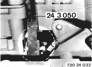 |
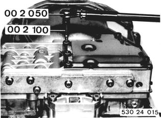
Only for New Version with Torx Bolts: Tighten Torx bolts with Special Tools 00 2 100 and 00 2 050¹).  ¹) See Specifications for tightening torque ¹) See Specifications for tightening torque
|  |
Install gasket on oil pan. Install magnet next to oil filter screen. New version will have two magnets. | 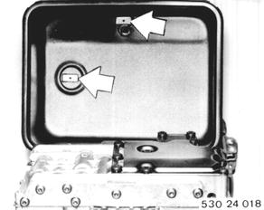 |
Bolt oil pan, using holders. Short arm of holder presses down on oil pan. | 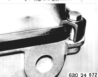 |
Vehicles after change point in 1982 DISASSEMBLING/ASSEMBLING TRANSMISSION Remove transmission 24 00 020. Remove torque converter 24 40 001. Mount transmission on assembly stand with Special Tool 24 0 150. Important! Tighten clamping bolts only finger tight to prevent damage on transmission case.  24 00 020 24 00 020 24 40 001 24 40 001
|  |
A) Disassembling: Detach oil pan. |  |
Detach valve body. Unscrew Torx bolts with Special Tool 00 2 100. | 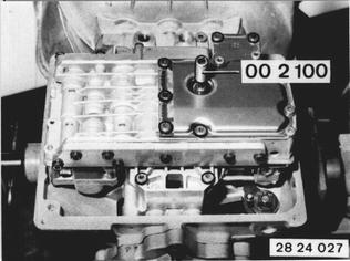 |
Lift out circlips. Remove springs (2 ... 5). |  |
Pull out dowel sleeve with Special Tool 24 2 050. |  |
Remove lockplate. Apply Special Tool 23 1 200. Hold output flange with Special Tool 23 1 150. Unscrew collar nut with Special Tool 23 1 210. Pull off output flange. |  |
Detach transmission extension. |  |
Loosen nut (6) and unscrew stud (7) about 3 turns. Pull off governor. |  |
Detach converter bell housing and transfer plate. Important! Thrust washer (8), needle bearing (9) and angled disc (10). |  |
Remove input shaft with clutch A. |  |
Remove plate carrier (11) for clutch A with plastic thrust washer (12) and metal thrust washer (13). |  |
Remove snap ring (14). When removing clutch B support (15) and seal (16) will also be pulled out. |  |
Pull out clutch B with two locally manufactured hooks. Sketch for local manufacture. Dimensions in mm. |  |
Remove snap ring (18). |  |
Pull out complete assembly. Centering plates (1), clutches C´, C and D (2), planet gear set with output shaft (3). Important! Parking lock must not be engaged. |  |
Important! Thrust washer (19), needle bearing (20) and angled disc (21). |  |
Pull centering plate (1), clutch unit (2) with clutches C´, C and D off of output shaft (3). |  |
Remove planet gear set with sun gear shaft. Important! Needle bearing (22) and thrust washer (23). |  |
 |
|
Hold angled disc (2) in position with grease on output shaft (angled side facing shaft). Install needle bearing and thrust washer on output shaft. |  |
Important! Keys (3 and 4) must be center of cylinder groove. Parking lock must not be engaged. Guide entire output unit into transmission case that 4 oil bores in output unit are aligned with bores in bottom of transmission case. |  |
Install snap ring (5). |  |
Install clutch B. |  |
Install seal (6) and press against stop with support (7). Install snap ring (8). |  |
Install plastic thrust washer with grease that tabs engage in openings of cylinder A. |  |
Hold metal thrust washer in plate carrier with grease. |  |
Install plate carrier (9) in clutch A by moving back and forth slightly. Install clutch A in transmission case. |  |
Install angled disc (10) on input shaft with collar facing needle bearing (11). |  |
Stick thrust washer (12) and gasket (13) on converter bell housing. Push converter bell housing on input shaft and bolt. |  |
Check axial play of input shaft. Specification: 0.3 ... 1.5 mm (0.012 ... 0.060´´). |  |
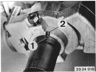
Compress piston rings slightly and push governor on to governor flange. Important! Punch mark (1) on output shaft must align wigh opening (2) on governor hub. Mount governor*.  * See Specifications * See Specifications
|  |
Lubricate sealing lip of radial oil seal with ATF. Attach transmission extension and output flange. Install collar nut with Curil K2 or Loctite 572; Tighten collar nut*. Place lockplate on nut and lock in groove of output flange.  * See Specifications * See Specifications
|  |
Knock in 4 dowel sleeves against stop with a suitable mandrel. |  |
Install and lock springs. Both short springs (1 and 2) will be on selector lever end. |  |
Install valve body that clamp on selector valve can be attached in operating arm of pawl. Pull transmission cable slightly for this purpose so that accelerator cam does not clamp with throttle pressure valve. |  |
Tighten valve body bolts only finger tight. | 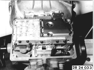 |
Align valve body with Special Tool 24 3 050. If this special tool is not available, distance from valve body case to pin in throttle pressure piston must be 11.5 mm (0.453´´). Tighten valve body with bolts in this position. | 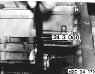 |
Tighten torx bolts to specified torque* with Special Tools 00 2 100 and 00 2 050.  * See Specifications * See Specifications
|  |
Install gasket on oil pan. Install magnets (1 and 2). Watch installed position. | 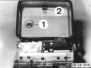 |
Tighten oil pan bolts with brackets. Short leg of bracket presses on oil pan. Tightening torque*.  * See Specifications * See Specifications
|  |
BMW 628csi - M635csi (M6)»24 - Transmission-automatic»24 00 080 - Transmission - disassembling and assembling