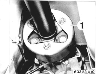
 |
|
Apply Special Tool 26 1 011. Unscrew bolts. Installation: Use stop nuts only once. | 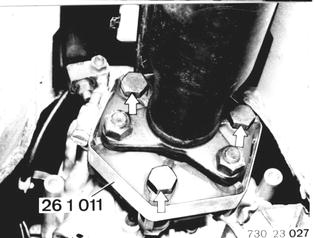 |
Tighten Special Tool 26 1 011 until bolts can be removed by hand. | 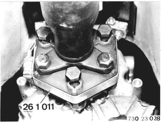 |
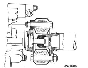
Installation: Tichten nuts to specified torque¹) with a standard 19 mm socket and torque wrench. Important: Only tighten nuts (never bolts) to prevent stress in Giubo coupling. Remove special tool only after tightening nuts.  ¹) See Specifications ¹) See Specifications
| 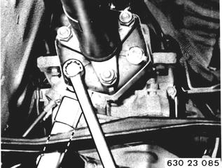 |
Disconnect center bearing. Installation: Preload center bearing forward by distance (A) = about 2 mm (0.080´´). | 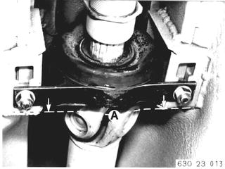 |
Bend propeller shaft down and pull it out of centering pin on transmission. Installation: Check center, lubricating with Longerm 2 if necessary. Replace a damged center. Align propeller shaft with Special Tool 26 1 000 (see 26 11 000).  26 11 000 26 11 000
|  |
Disconnect bracket (1) on transmission. Detach clutch slave cylinder. Line remains connected. | 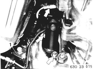 |
Support transmission. Remove cross member (1). Lower transmission to front axle carrier. | 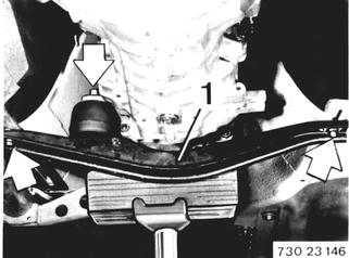 |
Disconnect transmission at clutch housing and remove toward rear. | 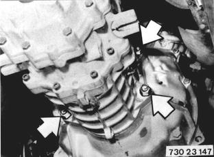 |
Installation: Move release lever to installed position with the clutch slave cylinder. Align clutch thrust bearing. Pack lubricating groove (N) with Molykote Longterm 2. Non-conformance could cause thrust bearing to seize on guide sleeve. Engage gear prior to installing transmission. Guide transmission guide sleeve into thrust bearing carefully. Turn output flange until input shaft slides into drive plate. Remove clutch slave cylinder again. Mount transmission. | 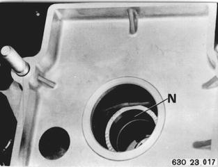 |
Vehicles after change point in 1982 REMOVING AND INSTALLING TRANSMISSION Remove exhaust assembly 18 00 020. Remove heat shield. Unscrew coupling on transmission.  18 00 020 18 00 020
| 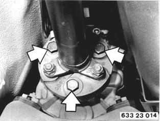 |
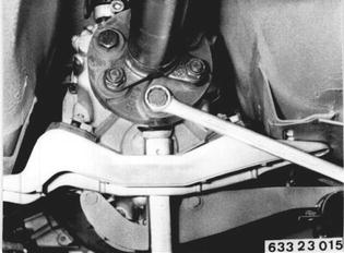
Installation: Replace stop nuts. Tighten nuts with a standard 19 mm socket and a torque wrench. Tightening torque*. Important! Only tighten nuts (never bolts) to avoid stress in coupling.  * See Specifications * See Specifications
|  |
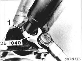
Version with Screw-On Ring: Unscrew screw-on ring (1) several turns. Installation: Tighten screw-on ring (1) with Special Tool 26 1 040 after finishing installation. Tightening torque*.  * See Specifications * See Specifications
|  |
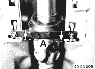
Unscrew center mount. Installation: Preload center mount forward by distance A = 4 to 6 mm (0.157 to 0.236´´). Tightening torque*. Bend propeller shaft down and pull off of centering pin. Important! Suspend propeller shaft from car with a piece of wire.  * See Specifications * See Specifications
|  |
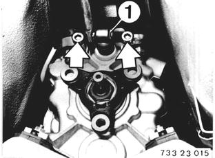
Pull off wires on reverse gear switch. Unscrew shift console on transmission. Importent! Self-locking bolts - these bolts will be hard to unscrew. Installation: Always replace self-locking bolts. When tightening, make sure brackets are horizontal to the shift console (shift lever noise). Tightening torque*. Lift out retainer (1). Remove washer. Pull out selector rod.  * See Specifications * See Specifications
|  |
Version with Shift Arm: Lift spring (1) out of holder (2) on case with a screwdriver and swing up. Pull out shaft bolt. Installation: Lubricate shaft bolt lightly with Molykote Longterm 2. | 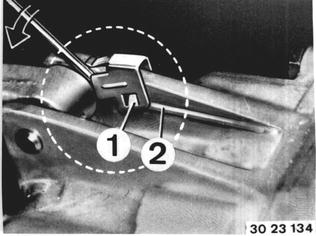 |
Only for Version with Cover: Unscrew cover (1). | 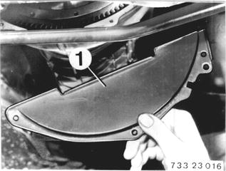 |
Version with DME: Unscrew bolts. Pull out speed sensor (3) and reference mark sensor (4). Important! - Installation: Check installed position. Plugs must no be mixed up. Install speed sensor (3) in bore (D) and reference mark sensor (4) with ring (5) in bore (B). Engine cannot be started, if plugs are mixed up. | 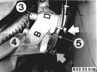 |
Installation: Check O-ring. Install sensors with Molykote Longterm 2. Important! Face of DME sensors must be free of grease and dirt. | 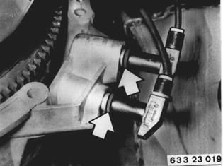 |
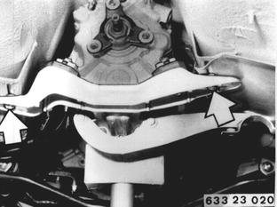 |
|
Unscrew clutch slave cylinder. Line remains connected. Bleeder screw faces down. | 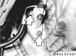 |
Pull off wires on reverse gear switch. Lift wires out of holders. | 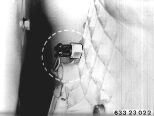 |
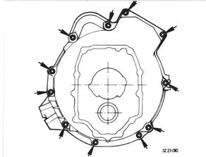
Unscrew transmission on engine. Use Torx socket for Torx bolts. Important! - Installation: Use washers on version with Torx bolts to avoid an increase in breaking-loose torque. Tightening torque*. Remove transmission toward rear. Check oil level.  * See Specifications * See Specifications
|  |
BMW 628csi - M635csi (M6)»23 - Transmission-manual»23 00 022 - Transmission - removing and installing