Vehicles after change point in 1982 Application Information: This survey can be apllied for troubleshooting and consequently finding sources of defect more quickly. The checked causes of malfunction might not always be sufficient to eliminate a defect, so that under certain circumstances additional tests could be necessary. Testing instructions refer to the BMW SERVICE TEST, e.g. engine test/test step 05 (P 05) or a multimeter function (M). See operating instructions for connections. | |
 |
|
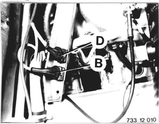
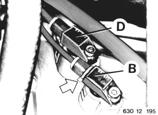
Turn engine with the starter. Check resistance (M 06) and oscillograph (M 22/23) on disconnected pulse sensor plug with BMW service test unit, see 12 14 510.  12 14 510 12 14 510
|  |
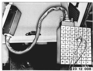
Check wires leading to DME control unit: Take off trim panel. Pull off plug on control unit and connect on universal adapter ** with (35-pin) test lead - see illustration. Check power flow (M 06) in wires on specified pins***. ** Source: HWB *** See engine wiring diagram | 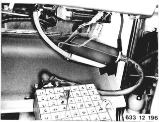 |
Test 2 - IGNITION COIL Check wires for tight fit. Check connection plate and ignition lead contacts for traces of burning, cracks and oxidation. Check code number* of ignition coil - see 12 13 009. Check resistance* (M 06) and inductivity* (M 07) of primary and secondary coils - 12 13 011.  *See Specifications *See Specifications 12 13 009 12 13 009 12 13 011 12 13 011
|  |
Test 3 - SPARK PLUGS Check spark for tight fit and leaks. Check insulator for signs of leakage current. Check spark plug type* and electrode gab*.  *see specifications *see specifications
| |
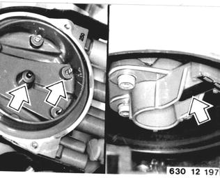
Test 4 - HIGH VOLTAGE DISTRIBUTOR Check distribution cap and rotor for correct fit, damage and hairline cracks as well as signs of burning. Check wire connections for oxidation and good contact - see 12 11091/111. Check resistance* (M 06) from distributor peak to corresponding contact in distributor cap. Resistance must be approximately 0 ohm. Check resistance* (M 06) of distributor rotor.  *See Specifications *See Specifications 12 11 091 12 11 091 12 11 111 12 11 111
|  |
Test 5 - IGNITION LEADS AND LEAD CONNECTORS Check spark plug connectors and shielded connectors for damage, tightness and good contact. Bend ignition leads in a tight radius and check for cracks. Check resistance* (M 06) of spark plug connectors and ignition leads.  *see specifications *see specifications
|  |
Test 6 - DME CONTROL UNIT AND POWER SUPPLY Check code number* and manufacturing date* of DME control unit - see group 13. Check power supply**: Pull off plug on control unit and connect universal adapter*** with (35-pin) test lead. Car wire harness plugs remain connected. Turn on ignition. Check voltage on pins**, e.g. on connections 17 (-) and 35 (+). If test results indicate the necessity to replace the control unit, first make the periphery test with an universal adapter***. **See engine wiring diagram ***Source: HWB  *See Specifications *See Specifications
|  |
Test 6 - DME CONTROL UNIT AND POWER SUPPLY Pull off relay 2 and bridge terminals 87 and 30 with a piece of wire. This supplies power to the control unit. Check activation** for relay 2: Turn on ignition. Terminals 85 (-) and 86 (+) should have voltage (approx. 12 V). **See engine wiring diagram | 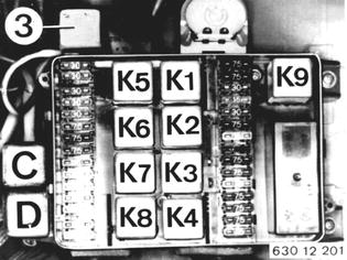 |
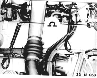
Test 6 - DME CONTROL UNIT AND POWER SUPPLY If necessary, check ground point and plug connection (to car wire hareness) - see figure. | 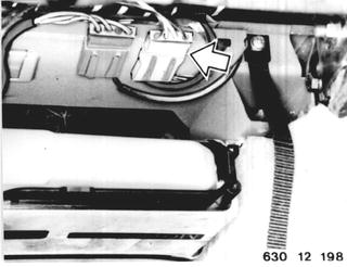 |
Test 17/18 - EXHAUST SYSTEM / CATALYTIC CONVERTER Check exhaust system and catalytic converter for damage, tight fit and leaks - see Group 18. | 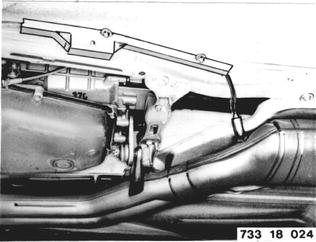 |
Test 19 - CRANKCASE VENT Check hoses for crankcase vent and oil dipstick for tight fit and leaks. | 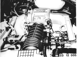 |
Test 20 - COOLING SYSTEM Check coolant level and concentration**. If necessary, fill and bleed cooling system - see Group 17. **See Service Information of Gr. 00 | 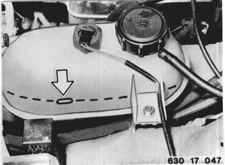 |