 |
|
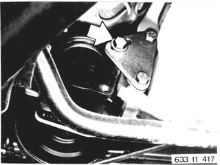
Disconnect power steering pump at front. Pressure hoses remain connected. Installation: Tighten drive belt - standard belt should give under thumb pressure applied midway between two pulleys by 5 to 10 mm (0.197 to 0.394´´) and open flank belts by 2 to 3 mm (0.080 to 0.120´´). | 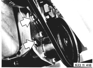 |
Unscrew bracket (1). Detach compressor and suspend it with wire. Hoses remain connected. Detach pulley with vibration damper 11 23 000.  11 23 000 11 23 000
| 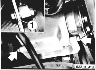 |
Unscrew bolts (2). Pull off plug (3). Take off clamp (4). Lift out wire and remove air cleaner housing. |  |
Up to 1980 Models: Disconnect wires 4, 1 and 15 at ignition coil. Installation: red black to terminal 15 black to terminal 1 Detach hose (2) at carbon filter. | 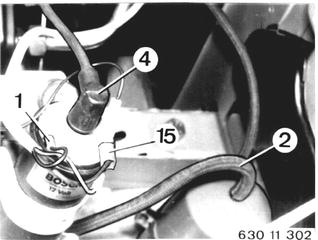 |
Only for BMW 633 CSi: Remove windshield washer fluid tank. Take off cap. Pull off plug (3). Pull off wires (4 ... 6) from resistors. Installation: Black/red wire to resistor 0.6 ohm - flat plug normal 6.3 x 0.8 Green wire to resistor 0.4 ohm - flat plug normal 6.3 x 0.8 Black/red wire to resistor 0.4 ohm - flat plug normal 4.8 x 0.8 Remove wire harness from holders. | 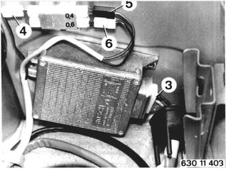 |
Detach or loosen vacuum hoses (3 ... 6) and hose (7) at brake pressure booster. Installation: 3 red from EGR valve/red electric switching valve 4 blue from EGR valve/pressure converter 5 red from throttle housing/elec. switch valve red 6 white from collector/distributor/electric switching valve/pressure converter | 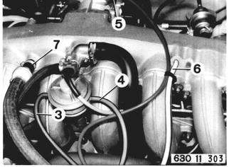 |
Detach vacuum hoses (8 ... 11) at booster blow- off valve and pressure converter. Installation: 8 white form booster blowoff valve/electric switching valve white 9 black from booster blowoff valve/electric switching valve blue 10 blue from booster blowoff valve/electric switching valve blue 11 red from pressure converter/EGR line Detach water hose (12) at fluid tank. Also refer to hose layout plan. |  |
Disconnect minus and plus leads at battery. Diconnect wire (13). Detach fuel supply and return hoses, and take them out of holder. For BMW 633 CSi: Detach fuel feed and return lines from pressure regulator and/or pipe. | 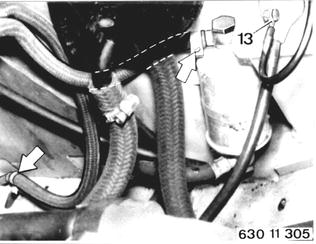 |
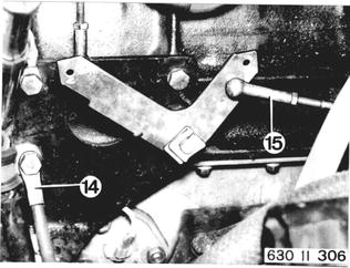
Detach ground wire (14). Detach accelerator linkage (15). Installation: Adjust accelerator cable 35 41 421.  * See Specifications * See Specifications
|  |
Detach coolant hoses (16 and 17). Important: Be careful not to mix up hoses. Hose (16) to cylinder head. Hose (17) to return line. | 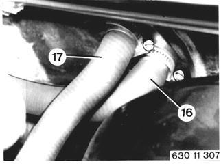 |
Pull off protective cap. Disconnect multiple plug (18) and relay carrier (19). Pull off speed switch. | 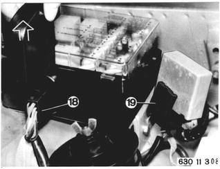 |
For BMW 633 CSi: Take off cap and pull off mulitple plug (18). Lift off relay carrier from power distributor. Pull off speed switch and relay. Remove wire harness from holders. | 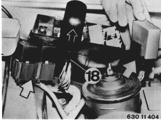 |
Pull off plugs (20 ... 23). Pull off black, red and white plugs form electric switching valves. Installation: Connect plugs that colors match. Pull out relay with carrier (24) toward outside. Disconnect wire harness from engine wall. Important: Plug (23) and relay (24) not applicable to BMW 633 CSi. | 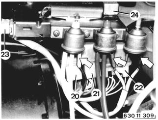 |
From 1980 Models: Disconnect ground wire at battery. Disconnect ground wire (1) at body. Disconnect positive wire (2). Remove cap (3). Pull off plug (4). Lift wire harness out of holders. | 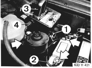 |
Detach ground wire (14). Detach accelerator linkage (15). Installation: Adjust accelerator cable 35 41 421.  * See Specifications * See Specifications
|  |
Lift out water tank. Disconnect wires at ignition coil. Pull off plug (1). Pull off plugs on resistors and take off wire harness. Pull off hose (2). | 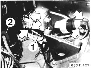 |
Separate plug connector (3) for oxygen sensor. Lift out relay (4). Loosen wire holders and take off wire harness. | 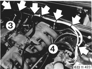 |
Detach coolant hoses (16 and 17). Important: Be careful not to mix up hoses. Hose (16) to cylinder head. Hose (17) to return line. |  |
Detach fuel feed hose (1) and fuel return hose (2). Detach coolant hose (3). | 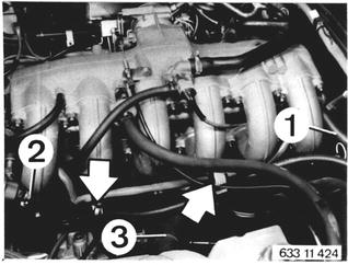 |
All Models: Open glove box. Pull off plastic sheet. Press back lock (25). Disconnect plug and wire (26). | 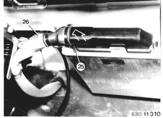 |
Connect Special Tool 11 0 020 front and rear. | 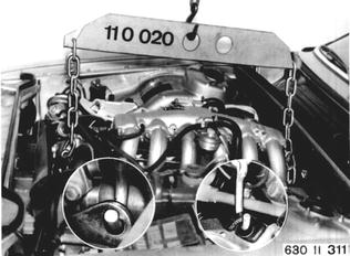 |
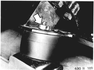
Detach left engine mount. | 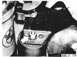 |
 |
|
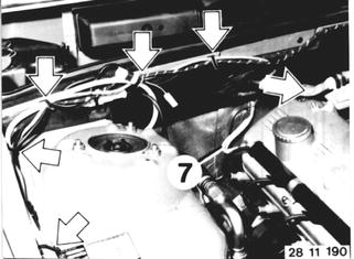
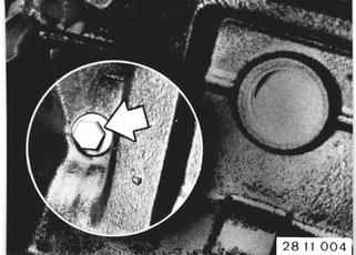
Vehicles after change point in 1982 REMOVING AND INSTALLING ENGINE Remove engine hood 41 61 000. Disconnect battery positive and negative leads. Unscrew ground strap (1) on body. Unscrew wire (2).  41 61 000 41 61 000
|  |
 |
|
Unscrew power steering pump. Pressure hoses remain connected. Installation: Tighten drive belt and check tightness with Special Tool 11 5 020. | 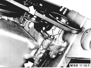 |
Unscrew compressor - see Group 64. Refrigerant hoses remain connected. Installation: Tighten drive belt and check tightness with Special Tool 11 5 020. | 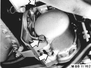 |
M 30 B 32: Pull off plug (2) and lift out wires. Pull out hoses (3 and 4). Loosen hose clamp (5). Disconnect wire. Unscrew nuts (6) and remove air cleaner with air flow sensor. | 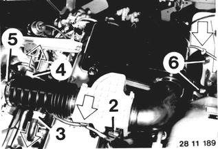 |
Pull off plugs on idle control unit and DME control unit in glove box. Run out wire harness into engine compartment. Disconnect ground wire (7). Disconnect oxygen sensor plug. Detach wire harness on firewall. | 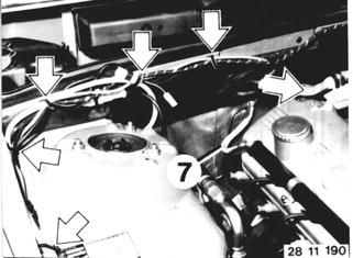 |
Pull off wire (4). Disconnect wires (1 and 15). Pull off wire (5) on solenoid. Disconnect plug (2). Disconnect wire harness. | 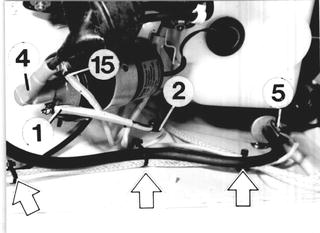 |
Lift out plug (1) and relay. Disconnect wire harness (2). | 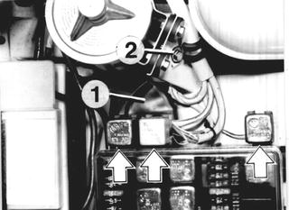 |
M 30 B 34: Pull off plug (2) and lift out wires. Loosen hose clamp (3). Disconnect wire (4). Pull off hose (5). Open clamp (6). Unscrew nuts (7) and remove air cleaner with air flow sensor. | 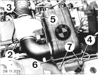 |
Pull off plug (8) on DME control unit in glove box. Disconnect plugs (9) and run out wire harness into engine compartment. Note: Refer to 13 61 000 or wiring diagram for connection of plugs.  13 61 000 13 61 000
| 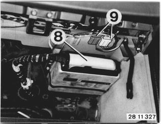 |
Pull off wire (4). Disconnect wires (1 and 15). Disconnect wire harness. | 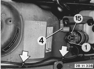 |
Disconnect ground wire (10). Disconnect wire harness and pull out into engine compartment. | 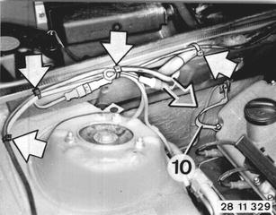 |
Pull off plug (11). Lift out relays (12 ... 14). Lift out diagnosis socket (15). Unscrew clamp (16). Disconnect wire harness. | 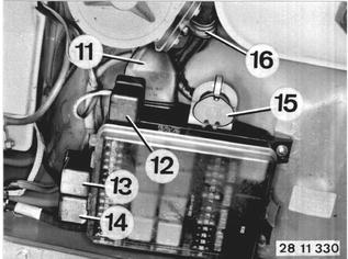 |
Detach wire harness for oxygen sensor on floor plate. | 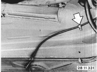 |
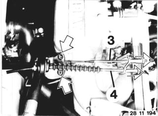
All Models: Disconnect throttle cable (3) and cruise control cable (4). Installation: Adjust throttle cable - see 35 41 421. Adjust cruise control cable - see Group 65.  35 41 421 35 41 421
|  |
Disconnect water hose (5) for expansion tank. Disconnect fuel return line (6). Lift wires out of clips. | 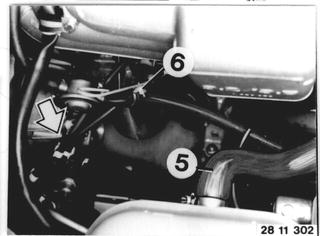 |
Disconnect fuel feed line (7) and heater hoses (8 and 9). | 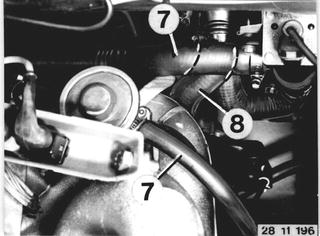 |
Pull off vacuum hose (8). | 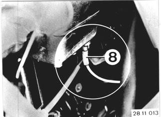 |
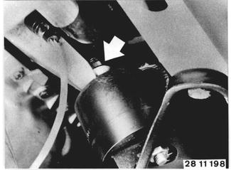
Disconnect water hose (2) and attach Special Tool 11 0 020 on engine. | 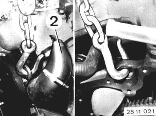 |
 |
|
Unscrew right engine mount. Lift out engine. Installation: Tightening torque*. Only M 30 B 32: Adjust engine idle speed/CO - see Group 13.  * See Specifications * See Specifications
|  |