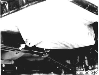
Changing Engine Oil and Replacing Oil Filter Engine at operating temperature. Unscrew filler cap. Unscrew oil drain plug from oil pan. Installation: Check oil drain plug and seal, replacing if necessary. Tightening torque¹).  ¹) See Specifications of Group 11 ¹) See Specifications of Group 11
|  |
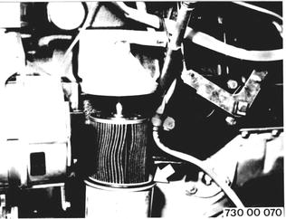
Unscrew oil filter housing. Clean oil filter housing. Replace oil filter cartridge. Installation: Check seals, replacing if necessary. Tightening torque¹).  ¹) See Specifications of Group 11 ¹) See Specifications of Group 11
|  |
Add 5.0 ltr. (10.5 pints) of brand name oil plus 0.75 ltr. (1.5 pints) for oil filter. Run engine and recheck oil level. Refer to Service Information of Group 11 for approved oils. | 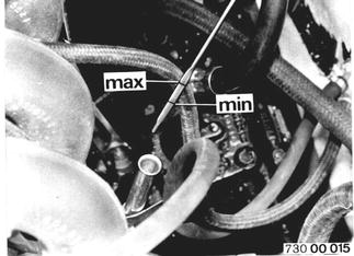 |
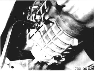
Checking/Correcting Manual Transmission Oil Level Unscrew oil filler plug. Add oil to raise level to lower edge of filler opening. Refer to Service Information of Group 23 for approved oils. Installation: Check filler plug, replacing if necessary. Tightening torque¹).  ¹) See Specifications of Groups 23 and 24 ¹) See Specifications of Groups 23 and 24 ¹) See Specifications of Groups 23 and 24 ¹) See Specifications of Groups 23 and 24
|  |
Checking/Correcting Automatic Transmission Oil Level Requirements: Car on level surface. Transmission at operating temperature. Selector level at "P". Engine running at idle speed. Amount of oil between min. and max. marks: Flat oil pan = approx. 0.25 ltr. (0.5 pints) Deep oil pan = approx. 0.40 ltr. (0.8 pints) Important: Never wipe off dipstick with a cloth losing lint. Refer to Service Information of Group 24 for approved ATF. Add ATF through funnel 24 0 080. | 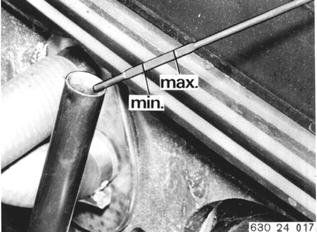 |
Checking Power Steering Oil Level With engine stopped, unscrew winged nut and take off tank cover. Oil level should be approx. 5 mm (0.2´´) above mark on tank wall. Start engine and, if necessary, add oil until level agrees with mark. Refer to Service Information of Group 32 for approved oils. |  |
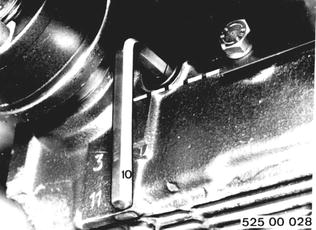
Checking/Correcting Final Drive Oil Level Unscrew oil filler plug. Add oil to raise level to lower edge of filler opening. Refer to Service Information of Group 33 for approved oils. Installation: Check seal, replacing if necessary. Tightening torque¹).  ¹) See Specifications of Group 33 ¹) See Specifications of Group 33
|  |
Checking/Correcting Brake Fluid Level Brake fluid level must be between min. and max. marks in transparent tank for brake system. Add brake fluid to raise level to max. marks. Refer to Service Information of Group 34 for approved brake fluids. Important: Replace brake fluid annually. | 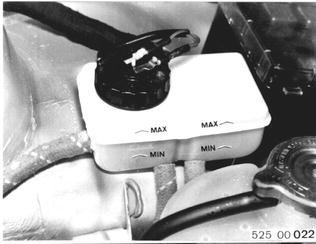 |
Checking/Correcting Battery Acid Level Lift off battery cover and unscrew caps. Acid level should be approx. 5 mm (0.2´´) above upper edge of plates in each cell or up to level mark visible in opening. Add distilled water, if level is too low. Keep top surface of battery dry and clean. Important: Be careful not to get acid and lead oxide from battery poles on clothing. Never work with an open flame near batteries. Danger of explosion! | 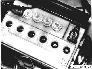 |
Checking Coolant Level and Concentration Add coolant to raise level to 2 cm (0.8´´) below radiator cap at most. Check antifreeze concentration. All year protection down to -25°C (-13°F). Refer to Service Information of Group 17 for approved antifreezes (longterm) and corrosion inhibitors. | 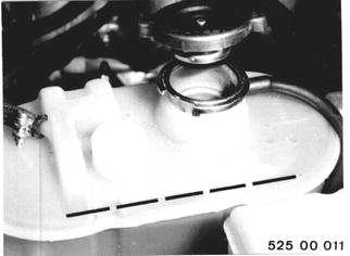 |
Adjusting Valve Play Turn engine with Special Tool 11 3 100. | 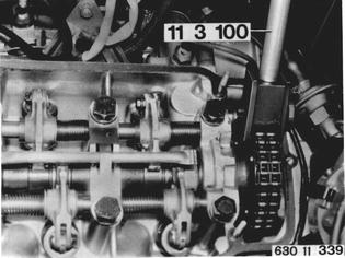 |
Adjusting order = firing order (1-5-3-6-2-4) in compression top dead center (TDC). Adjust valve play between valve and eccentric after loosening nut (1). Tighten nut (1) with Special Tools 11 1 150 and 00 2 050. Tightening torque¹). Intake and exhaust valve play on cold engine = 0.25 mm (0.010´´). | 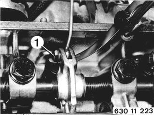 |
Tightening Engine Nuts and Bolts Left and right engine mounts to front axle carrier.....Nm 43-48, Ft.Lbs. 31-35 Left and right engine mounts to support bracket.....Nm 43-48, Ft.Lbs. 31-35 Left support bracket to engine (M 8).....Nm 22-24, Ft.Lbs. 16-17 Right support bracket to engine (M 10).....Nm 43-48, Ft.Lbs. 31-35 Thermo reactor to cylinder head.....Nm 30-33, Ft.Lbs. 22-24 Intake manifold to cylinder head.....Nm 30-33, Ft.Lbs. 22-24 Upper and lower timing case covers.....Nm 9-11, Ft.Lbs. 6.5-8 Oil pan to crankcase and timing case cover.....Nm 9-11, Ft.Lbs. 6.5-8 | |
Checking/Correcting Drive Belt Tightness A correctly tightened belt must give by distance (A) = 5 to 10 mm (0.197 to 0.394´´). Tightening Alternator Belt: Loosen alternator at tightening bar and upper mount. Swing out alternator and tighten bolts. |  |
Tightening Power Steering Belt: Loosen pump at holder and press down. Tighten mounting bolts. Open Flank Drive Belts: This type of drive belt should only give by 2 to 3 mm (0.080 to 0.120´´). | 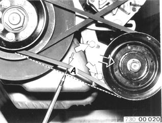 |
Checking/Correcting Tightness of Drive Belt for Air Conditioner Compressor | 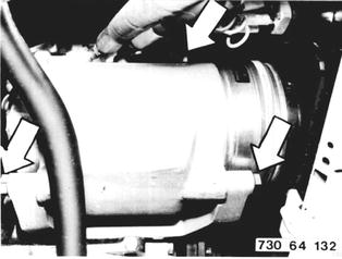 |
Performing SERVICE TEST Test Program 01 Engine Refer to operating instructions for BMW service test unit. | 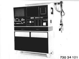 |
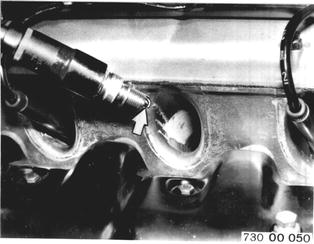
Checking or Replacing Spark Plugs Unscrew spark plugs. Clean or replace spark plugs covered with soot or oil. Electrode gap = 0.6 + 0.1 mm (0.024 + 0.004´´). Approved spark plugs¹). Tightening torque¹). Check spark plug wires and connectors for damage and tight fit.  ¹) See Specifications of Group 12 ¹) See Specifications of Group 12
|  |
Replacing Points Not applicable to engines with breakerless ignition systems. Take off distributor cap. Remove distributor rotor and dust cap. Important: Note tab on dust cover. | 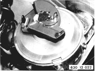 |
Disconnect flat male plug (1). Unscrew screw (2). Pull out contact breaker points. Installation: Clean new points to remove grease. Soak felt pad (3) in engine oil. Lubricate cam and bearing part (4) on contact breaker anvil with Bosch Ft 1 v 4 grease. | 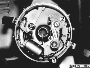 |
SERVICE JOBS ON FUEL INJECTION SYSTEM Checking Connections for Tightness or Leaks Check tightness of mountings and connections on air flow sensor, throttle housings, air collector, vibration tubes and throttle bypass valve, tightening if necessary. | 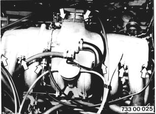 |
Tighten mounting clamps and screws of fuel injector holders. Check lines for correct routing and leaks. | 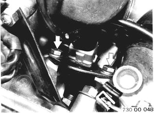 |
Lubricating Throttle Lever with Oil Check throttle valve for easy movement. Lubricate bearings with oil. Lubricate gate of throttle lever with grease. | 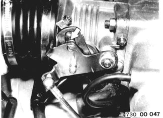 |
Checking or Replacing Air Filter Cartridge Open fasteners. Remove air filter cartridge. Installation: Watch installed position of the word "TOP". | 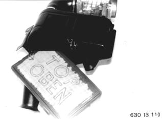 |
Checking Function of Fuel Injection System Check with BMW SERVICE TEST. Test Program 02 L-Jetronic. Refer to operating instructions for BMW service test unit. "or" Check with tester, Bosch No. 0684 100 202. See Group 13 for test values of different control units. |  |
Connect tester, Bosch No. 0684 100 202, to harness and control unit. Set selctor knob (1) at cylinder 6. Turn on ignition. Red indicator lamp (2) must be on during entire test. There is a defect in power supply cord, if this lamp goes out. The green indicator lamp (3) is a control for the injection impulses. Indicator lamp (3) will flicker while operating the starter. Indicator lamp (3) remains on as long as the contact breaker points are closed and the starter is not operated. Important: Always carry out test in sequence 1 through 10. Never carry out any one point without having first completed the previous points. Failure to observe this sequence could cause the fuel injection to function improperly and followup damage. All test points are made with the engine stopped or operated by the starter. | 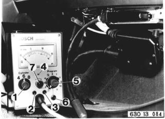 |
Adjusting Engine Idle Speed and CO Level Requires engine at operation temperature, i.e. min. oil temperature 60°C (140°F), correct ignition timing and valve play, perfect condition air filter cartridge and calibrated, warm CO tester. a) Engine Idle Speed Detach hose from collector to carbon filter and do not plug openings. Detach air hoise from air pump and insert plug. | 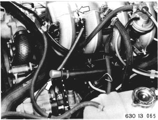 |
Adjust idle speed to 959 ± 100 rpm with screw (1). Turning screw (1) clockwise lowers idle speed. Engine must run as smooth as possible for adjusting. | 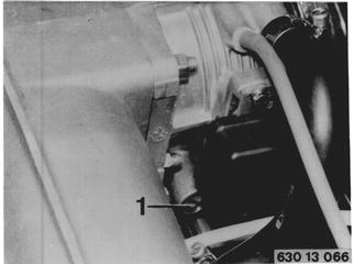 |
b) CO Level For CO level adjustments, note plug (3) on L-Jetronic control unit for high altitude correction. If car is operating in a high altitude area, plug (3) must be connected. | 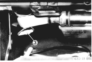 |
CO level at idle speed must be between 1.5 and 3.0% by volume. | 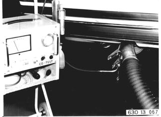 |
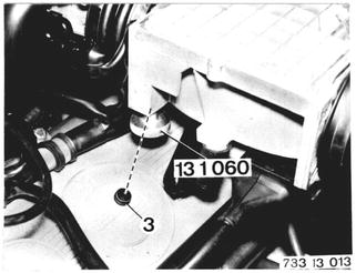
CO level at idle speed: 1.5 to 3.0% by volume. CO level too low: a) Leak in intake system after air flow sensor. b) Auxiliary air valve defective 11 61 090. c) Fuel pressure regulator defective 13 51 200. d) Fuel filter partially displaced 13 32 051. e) Check fuel pump pressure 13 31 029. f) EGR valve leaks 11 71 501. g) Exchange control unit for testing 13 61 000. h) Check function of fuel injection electric equipment with tester, Bosch 0684 100 202 - 13 60 009. Positions a) ...h) not cause: Remove end cap (3) with an angled scribe or similar tool. Correct CO level to specifications with ide air screw in air flow sensor, using Special Tool 13 1 060. CO level too high: a) Oil dipstick not tight enough in guide tube. b) Too much oil in crankcase. c) Intake and exhaust valves leak. d) Exchange air flow sensor for testing 13 62 000. e) Cold starting device won´t turn off 13 64 009. f) Check function of fuel injection electric equipment with tester, Bosch 0684 100 202 - 13 60 009. g) Fuel injectors leak 13 64 501. Positions a) ...g) not cause: Remove end cap (3) with an angled scribe or similar tool. Correct CO level to specifications with idle air screw in air flow sensor, using Special Tool 13 1 060.  11 61 090 11 61 090 13 51 200 13 51 200 13 32 051 13 32 051 13 31 029 13 31 029
|  |
SERVICE JOBS ON FUEL TANK AND LINES Cleaning Initial Fuel Filter in Suction Pipe Remove cover from trunk floor. Detach hoses (2 and 3). (2) to fuel pump (3) return line Pull off plug (4). br/ge = brown/yellow br = brown br/sw = brown/black | 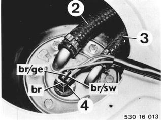 |
Loosen screws. Old Version: Turn fuel transmitter/suction tube anticlockwise with two crossed screwdrivers. | 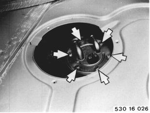 |
Clean fuel filter screen. Installation: Check gasket and round cord seal (19), replacing if necessary. Only when Replacing Fuel Transmitter: Remove transport guard (20). | 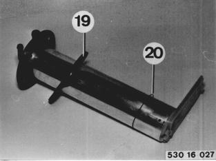 |
Replacing Main Fuel Filter Detach fuel hoses. Installation: Note direction of flow. | 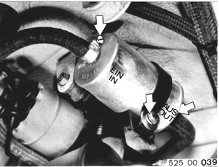 |
Checking Fuel Evaporation System Check tightness of hose lines and connections on fuel evaporation system. Check filter plate on carbon filter for plugging, replacing carbon filter if necessary. | 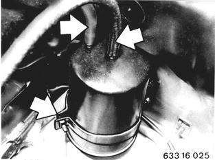 |
Checking Fuel System for Leaks Check tank cap and gasket, fuel tank and lines for leaks or damage (visual inspection). | 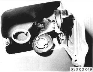 |
SERVICE JOBS ON COOLING SYSTEM Tightenning Hose Clamps on Cooling System Check coolant hoses for damage and correct routing. | 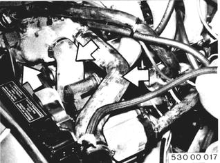 |
Tighten all hose clamps on radiator and engine. | 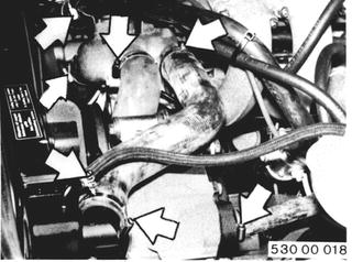 |
SERVICE JOBS ON EXHAUST SYSTEM Checking Exhaust System Check exhaust system for good condition, correct routing and leaks. | 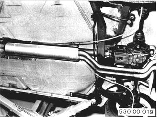 |
Check condition and tightness of exhaust suspension. | 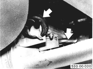 |
Check heat shields for tight fit or damage. | 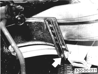 |
Checking EGR System Includes: Checking function of air pump, coasting blowoff valve, check valve, thermo valve, pressure converter and EGR valve, see 11 70 009.  11 70 009 11 70 009
| |
SERVICE JOBS ON PROPELLER SHAFT Checking Propeller Shaft for Wear Check rubber coupling for wear and distortion (visual inspection). | 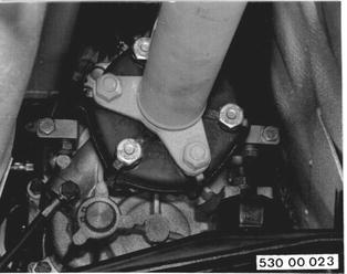 |
Check center bearing for cracks (visual inspection). | 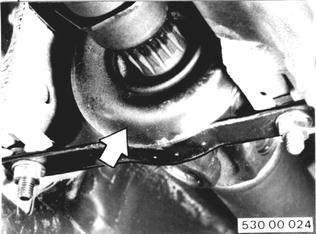 |
Check whether universal joints have play. | 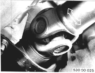 |
SERVICE JOBS ON FRONT AXLE Checking/Adjusting Front Wheel Bearing Play Remove and install grease cap with Special Tool 31 2 000. Remove cotter pin and unscrew castle nut. If necessary, replace grease packing. | 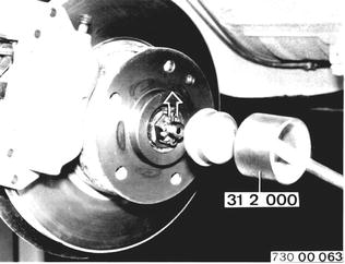 |
Tighten castle nut to 30 - 33 Nm ( 22 - 24 Ft.lbs.) while turning wheel hub continuously. This will settle tapered pins and bearing inner races. Grease causing play will also be forced out. Turn tightened bearing assembly at least 2 more turns. In so doing, do not loosen or tighten castle nut any further. | 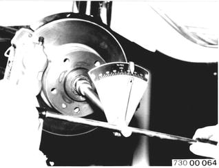 |
Loosen castle nut until there is axial bearing play, the hub being turned again. Tighten castle nut by max. 3 Nm (2 ft.lbs.), then turn back to nearest hole and lock with cotter pin. Checking Axial Bearing Play: Tabbed disc (1) must move without noticeable resistance. | 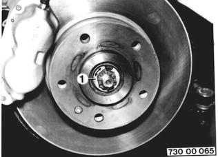 |
SERVICE JOBS ON STEERING Checking Condition of Front Axle Joints Check condition and play of front axle joints. Check bellows and covers. Check joint coupling. | 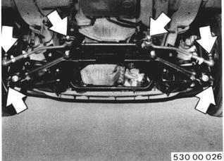 |
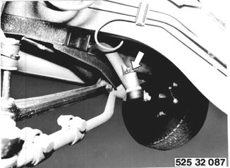
Checking Steering Gear Adjustment Important: The steering gear must be in good general condition before a pressure point adjustment can be made. Position front wheels to point straight ahead. Remove cotter pin and unscrew castle nut. Installation: Tightening torque¹). Lock castle nut with a cotter pin.  ¹) See Specifications of Group 32 ¹) See Specifications of Group 32
|  |
Press off center tie rod from steering drop arm with Special Tool 32 2 070. | 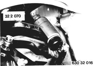 |
Take off BMW emblem. Find straight ahead position by taking half of total number of steering wheel turns. Turn steering wheel anticlockwise by about 1 turn. With Special Tool 00 2 000 mounted, turn clockwise past straight ahead position and take frictional torque reading. | 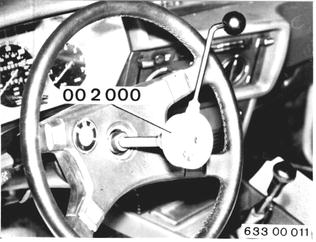 |
To adjust, turn steering wheel anticlockwise from straight ahead positon by about 1 turn. Important: In this position the worm cannot be pressed one-sided in its bearing by the steering sector shaft, which would erroneously show lack of play. Loosen locknut (1). Turn adjusting screw (2) until the frictional torque increases by 30 to 40 Ncm (2.6 to 3.5 in. lbs.) when passing straight ahead position. | 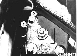 |
Checking Mechanical Steering Play (pressure point adjusted) Hold steering drop arm in straight ahead position with Special Tool 32 4 040. | 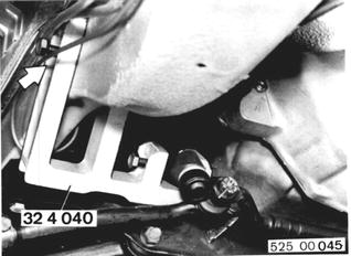 |
Open valve (2). Shut valve (1). Run engine having operating temperature at idle speed. Open valve (1). Read flow-through pressure. | 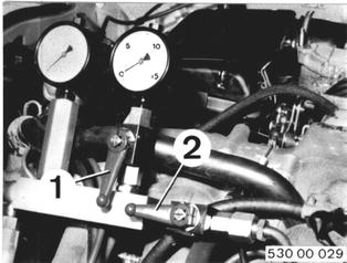 |
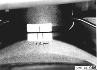
Paste strips of paper on steering wheel hub and casing upper section. Turn steering wheel anticlockwise carefully until pressure gage shows 1 bar (14 psi) more than the flow-through pressure. Mark position of steering wheel hub at (A). Turn steering wheel clockwise carefully until pressure gage 32 4 000 shows 1 bar (14 psi) more than flow-through pressure. Again mark position of steering wheel hub on (A). | 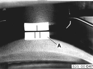 |
Total travel (B) must not exceed 7 mm (0.275´´). Check joint coupling, if 7 mm (0275´´) are exceeded. Replace steering gear, if joint coupling is not cause. Remove pressure gage 32 4 000. Fill and bleed hydraulic system 32 13 006.  32 13 006 32 13 006
|  |
Tightening Bolts and Nuts of Steering Power steering pump to engine.....Nm 22-24, Ft.Lbs. 16-17 Steering gear to front axle carrier.....Nm 43-48, Ft.Lbs. 31-35 Joint coupling to joint flange.....Nm 20-23, Ft.Lbs. 15-17 Joint flange to steering gear and steering spindle.....Nm 25-28, Ft.Lbs. 18-20 Tie rod bolts.....Nm 12-15, Ft.Lbs. 9-11 Tie rod castle nuts.....Nm 35-40, Ft.Lbs. 25-29 Tie rod arm to steering knuckle.....Nm 45-60, Ft.Lbs. 33-43 | |
SERVICE JOBS ON REAR AXLE Checking Output Shafts Check bellows of output shafts for damage and leaks. | 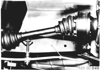 |
SERVICE JOBS ON BRAKE SYSTEM Checking Connections and Lines Check brake hoses for damage and tears. | 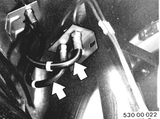 |
Check lines for correct routing, damage and corrosion. | 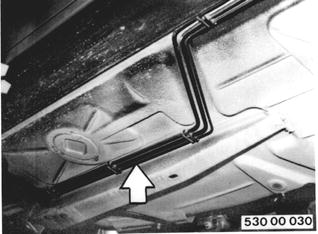 |
Check parking brake cables for damage, easy movement and correct routing. | 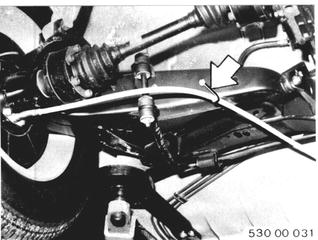 |
Checking Brake System for Leaks 1. Visual inspection. 2. Load brake pedal. If brake pedal drops slowly, check connections, brake master cylinder, wheel brake cylinders and brake calipers. | 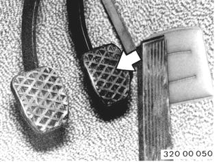 |
Checking Brake Pads/Liners 1. Front and Rear Disc Brakes: Remove wheels. Take off brake pads. Replace brake pads worn to minimum thickness of 2.0 mm (0.080´´) for pad without plate, or when "brake" lamp of check control comes on. Check surface condition of brake discs (visual inspection). Clean brake calipers. Check covers. Important: Draw off brake pad abrasion, being careful not to inhale it. | 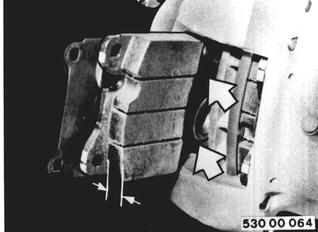 |
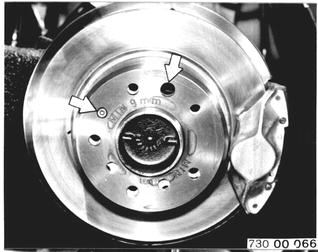
2. Parking Brake Liners: Remove and install rear wheel 36 10 300. Take off brake caliper, brake line remaining connected. Unscrew socket head bolt with a 4 mm wrench. Remove brake disc from axle shaft. Installation: Watch position of brake disc/axle shaft flange holes. Large hole of brake disc must align with large hole in axle shaft flange.  36 10 300 36 10 300
|  |
Check minimum thickness and condition of brake liners. Brake liners must not be less than 1.5 mm (0.060´´) at their thinnest point. Replace brake shoes, when liners reach 1.5 mm (0.060´´). | 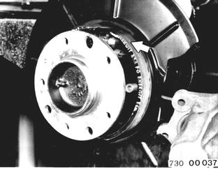 |
Checking Parking Brake Adjustment Pull up parking brake lever by 4 teeth. It must still be just barely possible to turn the wheels by hand. | 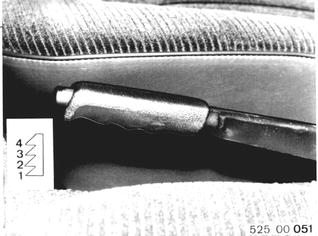 |
Adjusting Parking Brake: Pull off rubber cap. | 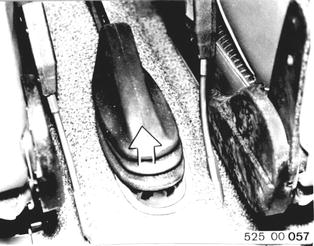 |
Unscrew nuts for parking brake cables enough that cables are slack. | 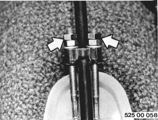 |
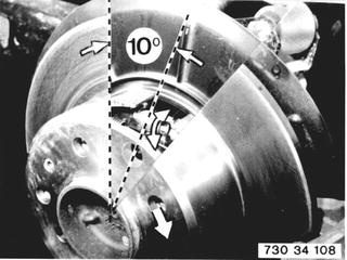
Unscrew and remove a wheel bolt from each rear wheel. Turn wheel that tapped bore is past the perpendicular by 10° in clockwise direction. Turn adjusting nut with a screwdriver to move out the parking brake shoes so that the brake disc can no longer turn. Then loosen the adjusting nut by 4 to 6 threads. Adjusting nut up = tighten. Adjusting nut down = loosen. Brake discs must turn freely. | 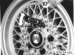 |
 |
|
Pull up parking brake lever by five teeth, starting from fully released position. Tighten adjusting nut (2) until wheel is stopped. Tighten locknut (1). Finally check whether both rear wheels turn easily, when parking brake lever is released. Pull up parking brake lever slightly and turn rear wheels by hand to check, whether adjustment of both cables is uniform. | 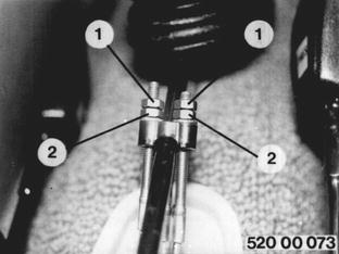 |
Tightening Bolts and Nuts Front caliper to steering knuckle.....Nm 80-95, Ft.Lbs. 58-69 Rear caliper to trailing arm.....Nm 60-67, Ft.Lbs. 43-48 | |
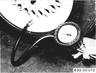
Checking Tire Pressure Values (Including Spare Wheel) Note temperature of tires. Note car load condition. Always take highest pressure for spare wheel tire. Install dust caps. Tire pressure values¹).  ¹) See Specifications of Group 36 ¹) See Specifications of Group 36
|  |
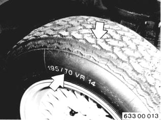
Inspecting Tires Tread depth of tires must not be worn to less than 3 mm (0.120´´) over entire tire width. Check tires for one-sided wear. Check tires and wheel rims for damage and correct size¹) and type.  ¹) See Specifications of Group 36 ¹) See Specifications of Group 36
|  |
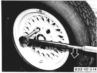
Checking Tightness of Wheel Bolts Check tightness of wheel bolts with a torque wrench. Tightening torque¹).  ¹) See Specifications of Group 36 ¹) See Specifications of Group 36
|  |
SERVICE JOBS ON BODY Checking Function of Locks Check function and adjustment of locks on doors, engine hood and trunk lid, adjusting if necessary. | 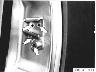 |
Lubricating Hinges with Oil/Grease Lubricate hinges on doors, engine hood and trunk lid with oil. Apply a light coat of grease to locks. | 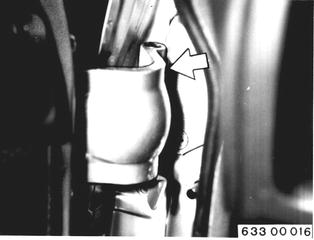 |
Tightening Bolts and Nuts Tighten bolts and nuts of doors, engine hood and trunk lid. | 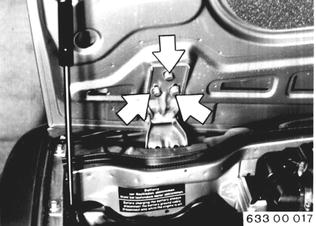 |
Checking Seat Belts Check that seat belts function correctly, are in good condition and anchored firmly. | 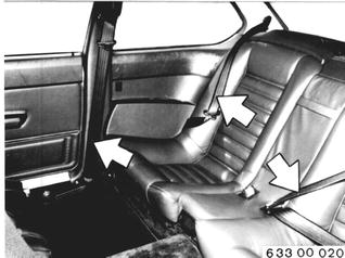 |
SEERVICE JOBS ON GENERAL ELECTRICAL SYSTEM Checking Function of Lights Check overnight lights, main and high beam headlights, stop lights, backup lights, rear fog light, license plate light, turn signals, hazard lights and horn for correct function, condensation and damage. | 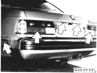 |
Check function of heater blower, indicator lamps, instrument lights, cigar lighter, inside lamp, glove box lamp, trunk and engine compartment lamps. | 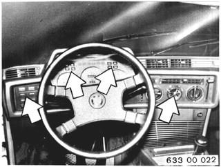 |
Checking Windshield Wipers Check function of wipe/wash intermittent action switch. Check windshield wiper arms and rubber blades. | 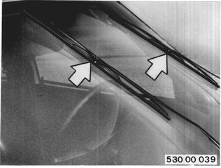 |
Check function of windshield washer system. | 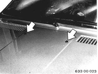 |
If stream does not hit within circle (A), the spray jet will have to be adjusted. A = 50 mm (2´´) B = 200 mm (8´´) | 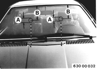 |
Final Inspection During test dirve check traffic safety and function of engine, cold start device, cooling system, transmission, final drive, steering and brakes. After adjustment of parking brake, pull up lever by 4 teeth and drive car about 400 m (400 yds.). After test drive check engine, cooling system, transmission, final drive, steering, brakes, radiator cap, fuel tank and lines for leaks. Visually inspect function of air conditioner and flow of refrigerant at receiver/drier sight glass. | |
Check engine idle speed and CO level - see 00-12. |  |
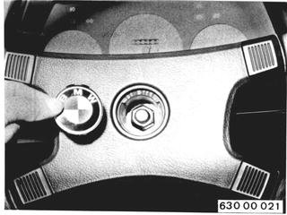
Check steering wheel straight ahead position and, if applicable, reposition steering wheel (not for free transfer inspection). Check steering wheel´s straight ahead position during test drive. To reposition steering wheel remove BMW emblem, unscrew nut, take off steering wheel and install in straight ahead position. Replace self-locking nut. Tightening torque¹).  ¹) See Specifications of Group 32 ¹) See Specifications of Group 32
|  |
Check clutch controls (not for free transfer inspection). Clutch pedal must not have any mechanical play, e.g. missing bearing bushings. After flooring the clutch pedal and waiting about 3 seconds, it should be possible to engage reverse gear without mechanical noise. Check brakes for one-sided pull or flattering during test drive. Watch indicator lamps. | 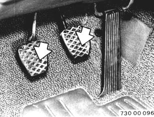 |
BMW 628csi - M635csi (M6)»00 - Maintenance and general information»00 00 239 - BMW inspection (beginning at 12,500 miles and then 12,500 mile intervals)