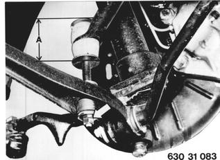
Vehicles before change point in 1982 REMOVING AND INSTALLING CONTROL ARM Remove and install front wheel 36 10 300. Detach stabilizer at control arm. Installation: Keep to specified torque¹) at control arm and distance (A) on pad for stabilizer. Distance A = 60 mm (2.362´´) only for singlepiece rubber pad (also refer to 31 35 000).  36 10 300 36 10 300 ¹) See Specifications ¹) See Specifications 31 35 000 31 35 000
|  |
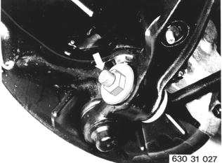
Unscrew tension strut nut on control arm. Installation: Tightening torque¹). Replace self-locking nuts. Install washers that convex side faces rubber mount.  ¹) See Specifications ¹) See Specifications
|  |
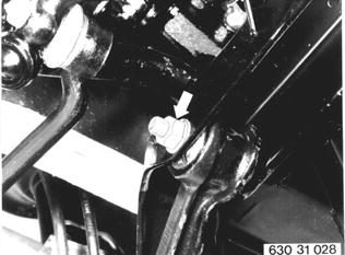
Detach control arm at front axle carrier and take it off of tension strut. Installation: Tightening torque¹). Replace self-locking nuts.  ¹) See Specifications ¹) See Specifications
|  |
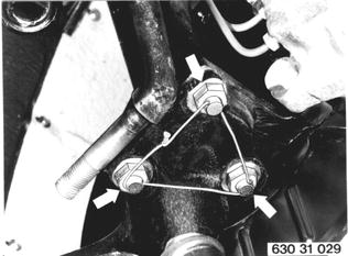
Remove lock wire. Unscrew bolts and take control arm off of spring strut. Installation: Tightening torque¹). Replace lock wire.  ¹) See Specifications ¹) See Specifications
|  |
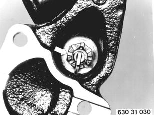
Remove cotter pin and unscrew castle nut. Installation: Tightening torque¹). Lock castle nut with cotter pin.  ¹) See Specifications ¹) See Specifications
|  |
Pull guide joint off of tie rod arm with Special Tool 00 7 500. | 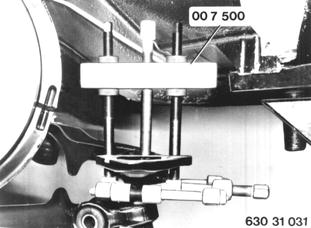 |
If axial play (S) is more than 1.4 mm (0.055´´), replace control arm. | 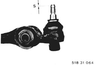 |
Important: Note the following when measuring control arms. Control Arms: Lemfoerder - left 1 103 981.2 - right 1 103 982.2 Ehrenreich - left 1 103 983.2 - right 1 103 984.2 | 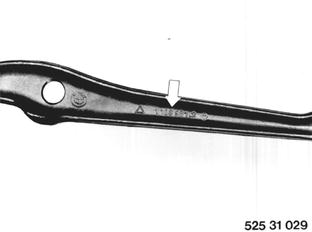 |