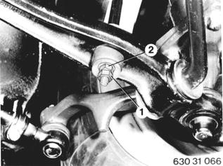
Vehicles before change point in 1982 REMOVING AND INSTALLING OR REPLACING STABILIZER Unscrew locknut (1) and mounting nut (2) on left and right sides. Pull off rubber rings (3 ... 6). | 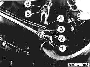 |
 |
|
1 Bolt M 8 x 160 2 Washer 3 Rubber ring 4 Stabilizer 5 Spacer 6 Nut M 8 7 Control arm | 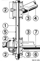 |
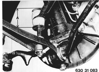
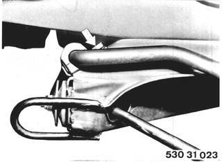
Single-piece Rubber Pads: Installation: Keep to specified torque¹) for control arm and distance (A) on pad for stabilizer. Distance A = 60 mm (2.362´´). Always replace rubber pad with a split version.  ¹) See Specifications ¹) See Specifications
|  |
Detach bracket and rubber mount. Installation: Slot in rubber mount faces forward. Only use rubber mount specified for pertinent stabilizer diameter. Stabilizer should not slide in rubber mount. Tightening torque¹).  ¹) See Specifications ¹) See Specifications
|  |
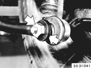
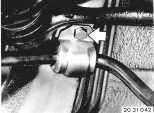
Vehicles after change point in 1982 REMOVING AND INSTALLING STABILIZER Disconnect thrust rods on the left and right sides. Counterhold on ball joint with a wrench. Installation: Tightening torque*.  * See Specifications of Gr. 31 * See Specifications of Gr. 31
|  |
 |
|
Press off holding clmaps and stabilizer. Installation: Slotted end of rubber mount faces rear. | 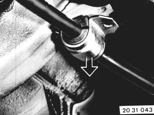 |