 |
|
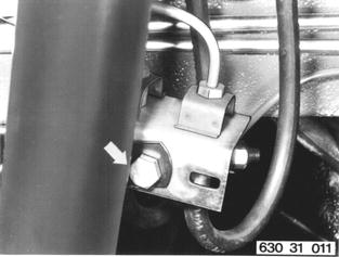
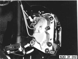
Detach and tie up caliper. Cables and brake lines remain connected. Installation: Tightening torque¹).  ¹) See Specifications ¹) See Specifications
|  |
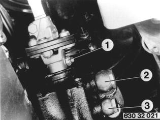
Remove bolt (1). Slide up connecting flange with steering column. Drain oil¹). Detach hoses (2 and 3) at steering gear. Plug openings with dust caps. Installation: Steering wheel and front wheels pointed straight ahead. Marks on box and steering shaft must align. Make sure bolt (1) is in locking groove of steering shaft. Replace self-locking nuts. Tightening torque¹). Bleed power steering 32 13 006.  ¹) See Specifications ¹) See Specifications 32 13 006 32 13 006
|  |
Detach left engine mount. Installation: Tightening torque¹). Make sure shoulder (1) of engine mount engages in proper opening.  ¹) See Specifications ¹) See Specifications
| 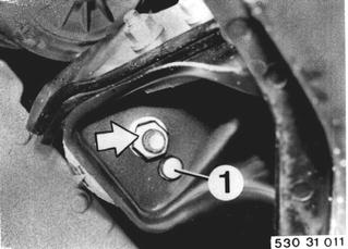 |
Detach right engine mount. Also detach clamp for oil hoses on models with an automatic transmission. Installation: Tightening torque¹). Make sure shoulder (1) of engine mount engages in proper opening.  ¹) See Specifications ¹) See Specifications
| 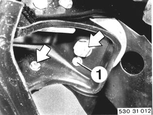 |
Unscrew bolts and remove heat shield. | 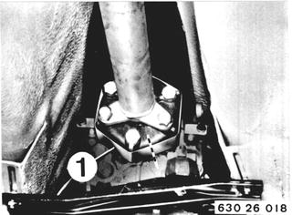 |
 |
|
Suspend engine from hoist with Special Tool 11 0 020. | 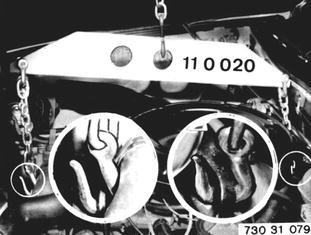 |
Support front axle carrier with a floor jack. | 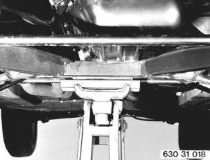 |
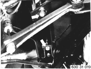
Detach left end of front axle carrier at frame member. Installation: Tightening torque¹).  ¹) See Specifications ¹) See Specifications
|  |
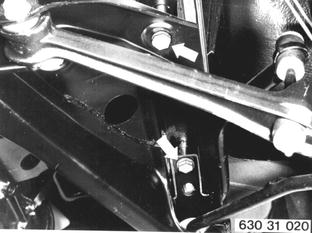
Detach right end of front axle carrier at frame member and lower assembly. Installation: Tightening torque¹).  ¹) See Specifications ¹) See Specifications
|  |
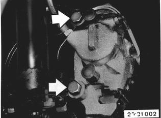
Disconnect and tie down left and right brake calipers. Brake lines remain connected. Installation: Tightening torque*.  * See Specifications of Group 34 * See Specifications of Group 34
|  |
Left side: Pull plug out of clamp and rubber grommet out of bracket. Disconnect ground wire. | 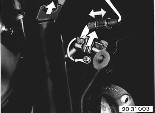 |
Remove Anti-lock sensor | 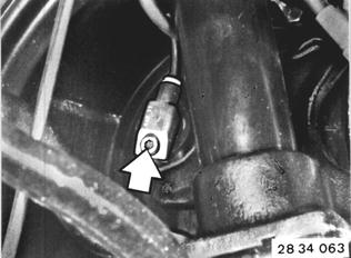 |
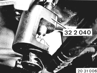
Remove cotter pin and unscrew castle nut. Press off tie rod on steering drop arm with Special Tool 32 2 040. Installation: Tightening torque*. Lock castle nut with cotter pin. On new type replace selflocking nut.  * See Specifications of Group 31/32 * See Specifications of Group 31/32
|  |
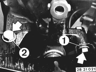
Unscrew steering gear mounting bolts (hold on nuts). 1 = Washer 2 = Washer (both sides) Tie down steering gear with a piece of wire. Lines remain connected. Installation: Replace self-locking nuts. Tightening torque*.  * See Specifications of Group 31/32 * See Specifications of Group 31/32
|  |
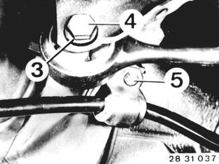
Unscrew bolts (4 and 5) on left and right sides. 3 = Washer (both sides) Installation: Replace self-locking nuts. Tightening torque* with car in normal position*.  * See Specifications of Group 31/32 * See Specifications of Group 31/32
|  |
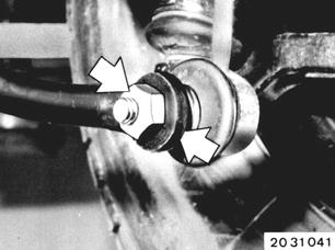
Disconnect push rods on left and right sides. Hold on ball joint with a fork wrench. Installation: Replace self-locking nuts. Tightening torque*.  * See Specifications of Group 31/32 * See Specifications of Group 31/32
|  |
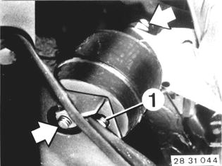
Unscrew engine mounts at bottom left and right. Loosen engine mount at top right. Installation: Check for correct installed position. Turning lock of mount is located in bore (1). Tightening torque*.  * See Specifications of Gr. 11/31 * See Specifications of Gr. 11/31
|  |
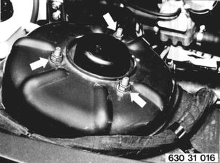
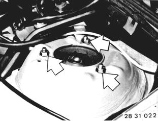
Support spring strut shock absorbers. Unscrew left and right mounts in wheel houses. Installation: Replace self-locking nuts. Tightening torque*.  * See Specifications of Gr. 11/31 * See Specifications of Gr. 11/31
|  |
Attach Special Tool 00 0 200 on engine. Use chain and hooks of Special Tool 11 0 020. | 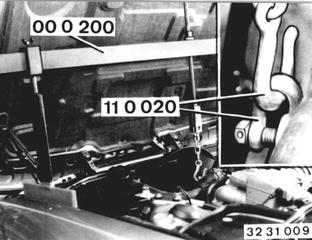 |
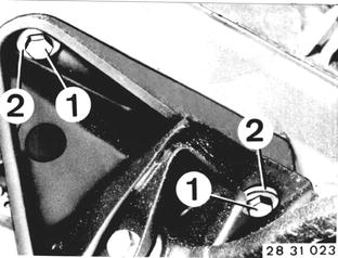
Place garage jack underneath front axle carrier. Unscrew engine carrier bolt (1) and lower front axle slowly. Caution! Spring struts must not be allowed to fall out or sag - ball joints would be damaged. Installation: Install bolts with washers (2). Tightening torque*.  * See Specifications of Gr. 31 * See Specifications of Gr. 31
|  |