Vehicles after change point in 1982 REPLACING MULTIPLE DISC CLUTCHES AND BRAKES Disassemble transmission 24 00 082. Important! Check transfer plate for installation of a venting valve (see 24 16 502) when repairing clutch A. If applicable, install a transfer plate with a venting valve. Clutch A: Press out input shaft (1). Check O-ring (2), replacing if necessary.  24 00 082 24 00 082 24 16 502 24 16 502
| 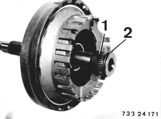 |
Compress clutch set and remove snap ring (3). Remove plate carrier (4). | 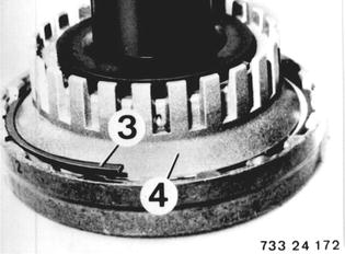 |
Lift out plate set and diaphragm spring. Note: Note number of steel and lined plates. | 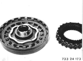 |
Press out clutch A piston with compressed air applied through bore. | 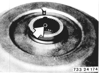 |
Installation: Replace O-rings (5 and 6). Lubricate O-rings with light coat of ATF to make installation easier. | 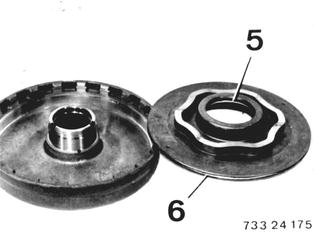 |
Installed Order of Plates: Insert noted number of removed steel and lined plates alternately, beginning with a spring and steel plate. 1 Spring plates 2 Steel plates 1.8 mm 3 Lined plates 4 Plate carrier | 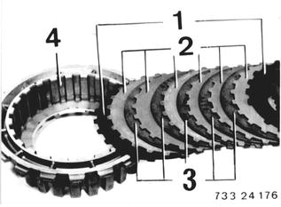 |
Place diaphragm spring in input shaft case with curved surface facing down. Insert plate set with plate carrier. Compress clutch set and insert snap ring. | 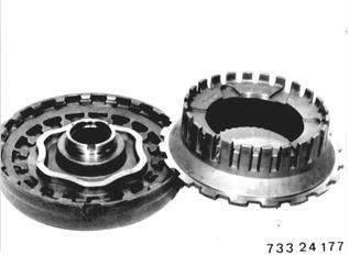 |
Clutch B: Remove snap ring (1). Remove steel and lined plates. Note: Note number of steel and lined plates. | 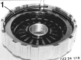 |
Bend open lockplate (2). Press down on diaphragm spring with Special Tool 24 2 030 and remove snap ring (3). Installation: Replace and lock lockplate. Insert diaphragm spring with curved surface facing up. | 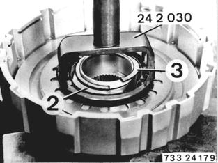 |
Press out clutch B piston with compressed air applied through oil bore. | 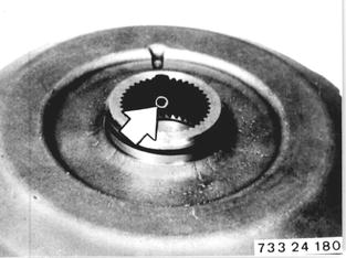 |
Installation: Check O-rings (4 and 5), replacing if necessary. Lubricate O-rings with a light coat of ATF to make installation easier. | 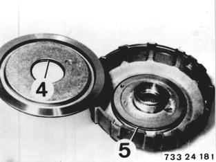 |
Installed Order of Plates: Insert noted number of removed steel and lined plates alternately, beginning with a steel plate. 1 Steel plates 1.8 mm (635 CSi = 2.1mm) 2 Lined plates 3 End plate 4.5 mm Important! Insert end plate with ground side facing lined plate. 4 Housing | 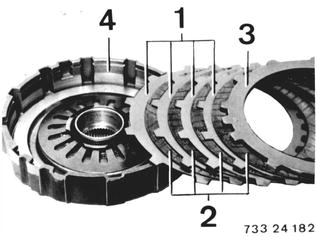 |
Clutch C´and C: To make this step easier, place complete set in a pipe with an inside diameter of 29 mm (1.142´´) and clamp in a vise. Remove Special Tool 24 0 040. Lift off centering plate (5). Installation: Bevelled beads must engage in bevelled openings. | 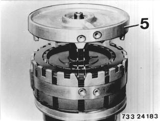 |
Press down on diaphragm spring with Special Tool 24 2 030 and lift out split retaining ring (1). Installation: Insert diaphragm spring with curved surface facing up. | 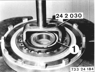 |
Press out clucht C´piston with compressed air applied through oil bore. Installation: Check O-rings (2 and 3), replacing if necessary. Lubricate O-rings with light coat of ATF to make installation easier. | 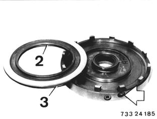 |
Remove all steel and lined plates. Note: Note number of steel and lined plates. Pull out one-way clutch (2). | 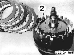 |
Press down diaphragm spring with Special Tool 24 2 030 and lift out split retaining ring (2). Installation: Insert diaphragm spring with curved surface facing up. | 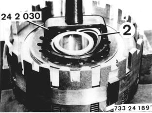 |
Press out clutch C piston with compressed air applied through oil bore. Installation: Check O-rings (3 and 4), replacing if necessary. Lubricate O-rings with a light coat of ATF to make installation easier. | 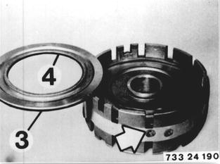 |
Install one-way clutch. Important! Bent over tabs or word "oben" must be seen. | 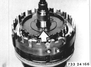 |
C Installed Order: Insert noted number of removed steel and lined plates alternately, beginning with a steel plate. 5 Steel plates 1.8 mm Important! Steel plates for BMW 635 CSi have different thicknesses (1.5 and 2.1 mm). The thinner (1.5 mm) steel plate is installed on the piston end. 6 Lined plates. 7 End plate 4.5 mm | 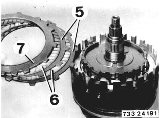 |
Important! Insert end plate that center tooth of three teeth group engages in opening of cylinder. | 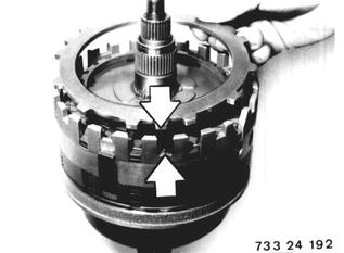 |
C´Installed Order: Insert noted number of removed steel and lined plates alternately, beginning with a lined plate. 5 Steel plates 1.8 mm Important! Steel plates for a BME 635 CSi have different thicknesses (1.5 and 2.1 mm). The thinner (1.5 mm) steel plate is installed on the piston end. 6 Lined plates | 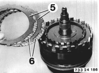 |
Important! External splines of steel plates must not be placed in bevelled openings of cylinder. | 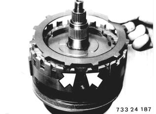 |
Clutch D: Clutches C´and C removed. Lift clutch member with clutch D off of planet gear set. | 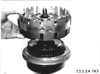 |
Remove snap ring (1). Remove steel and lined plates. Note: Note number of steel and lined plates. | 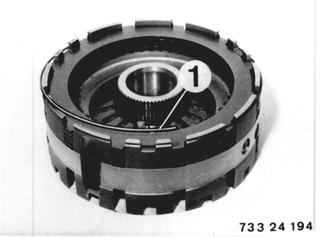 |
Prress down on diaphragm spring with Special Tool 24 2 030 and lift out snap ring (2). Installation: Insert diaphragm spring with curved surface facing up. | 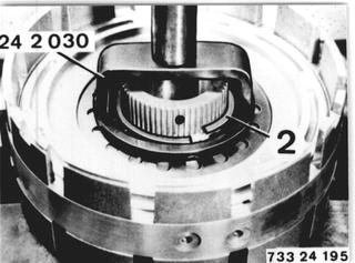 |
Press out clutch D piston with compressed air applied through oil bore. Installation: Check O-rings (3 and 4), replacing if necessary. Lubricate O-rings with a llight coat of ATF to make installation easier. | 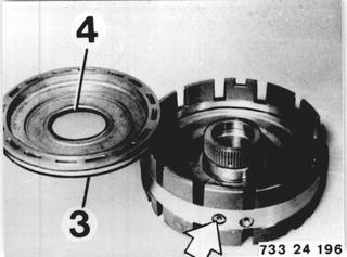 |
Place planet plate with one-way clutch on hub of cylinder D. | 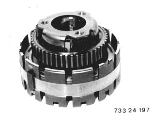 |
Installed Order of Plates: Insert noted number of removed steel and lined plates alternately, beginning with a steel plate. 5 Steel plates 1.8 mm 6 Lined plates 7 End plate 1.2 mm | 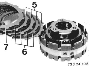 |
Disassemble planet gear set. Remove support ring (1). Installation: Mount support ring with fins facing down. | 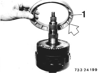 |
Take off planet gear set (2). | 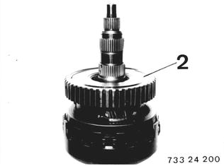 |
Pull out sun gear shaft (3). | 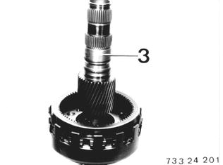 |
Remove axial bearing (4) and thrust washer (5). | 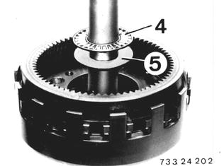 |
Lift out snap ring (6). | 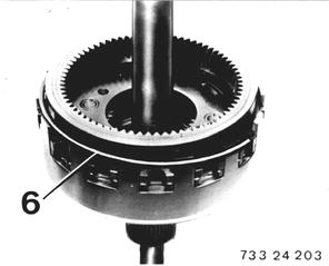 |
Remove hollow gear (7) and planet plate (8). | 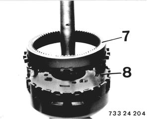 |
Remove thrust washers (9) and axial bearing (10). Take off spacer (11). | 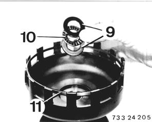 |
Lift out snap ring (12). Take off hollow gear (13). | 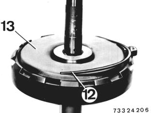 |
Clutches E and F: Remove sun gear (1) and planet carrier (2). | 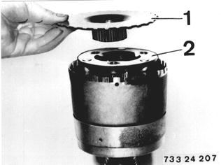 |
Remove angled washer (3), axial bearing (4) and thrust washer (5). Installation: Install angled washer (3) with collar facing planet carrier. | 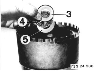 |
Take off Special Tool 24 1 010. | 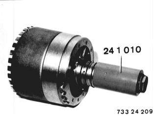 |
Lift cylinder F off of cylinder E. | 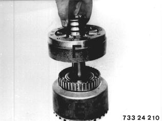 |
Lift off cylinder E on output shell. | 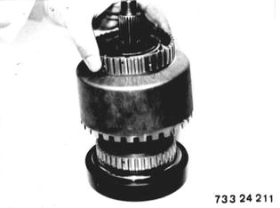 |
Take off thrust washer (6), axial bearing (7) and steel/copper angled washer (8). | 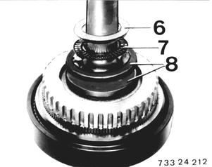 |
Installation: Mount cylinder E and turn until it rests on stop. Clyinder must rest on copper angled washer. When holding ouput shaft it must now be possible to turn cylinder E clockwise. It should lock in opposite direction. | 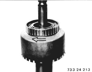 |
Clutch F: Lift out snap ring (1). | 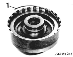 |
Remove plate set. Note: Note number of steel and lined plates. | 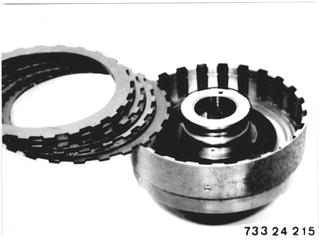 |
Remove piston for clutch F. Press down on diaphragm spring with Special Tool 24 2 020, and lift out split retaining ring (1). Installation: Insert diaphragm spring with curved surface facing up. | 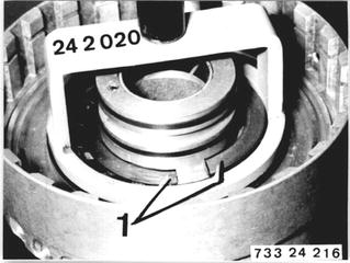 |
Press out piston for clutch F with two suitable mandrels. Installation: Check O-rings (2 and 3), replacing if necessary. Lubricate O-rings with a light coat of ATF to make installation easier. | 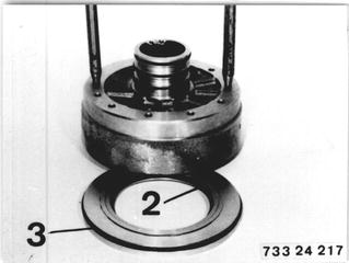 |
Installed Order of Plates: Insert noted number of removed steel and lined plates alternately, beginning with a steel plate. 1 Steel plates 2.1 mm 2 Lined plates 3 End plate 4.5 mm |  |
Clutch E: Lift out snap ring (1). | 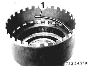 |
Remove plate set. Note: Note number of steel and lined plates. | 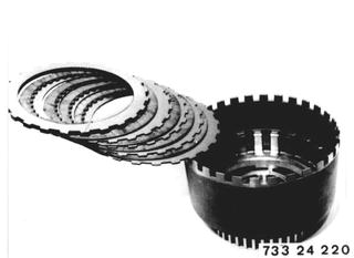 |
Remove piston for clutch E. Press down on diaphragm spring with Special Tool 24 2 020 and remove the split retaining ring (2). Installation: Insert diaphragm spring with curved surface facing up. | 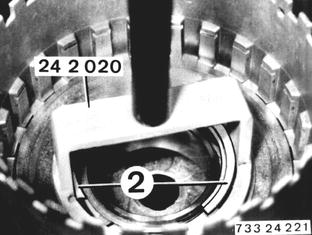 |
Lift off thrust cover (3). Press out clutch E piston with compressed air applied through oil bore. Installation: Check O-rings (4 and 5), replacing if necessary. Lubricate O-rings with a light coat of ATF to make installation easier. | 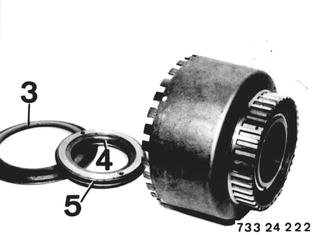 |
Installed Order of Plates: Insert noted number of removed steel and lined plates alternately, beginning with a steel plate. 1 Steel plates 1.5 mm 2 Lined plates 3 End plate 4.5 mm | 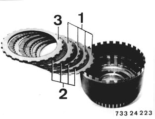 |
Connect cylinders E and F by turning. Collar on output shaft must protrude by distance A = approx. 10 mm (0.394´´). Apply Special Tool 24 1 010. | 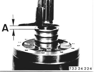 |
Removing One-way Clutch: Lift out snap ring (1). | 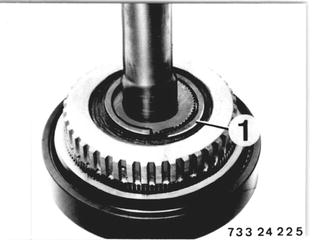 |
Press out output shaft (2). | 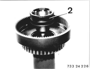 |
Lift off carrier (3). | 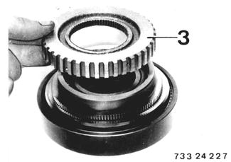 |
Pull or press off one-way clutch. | 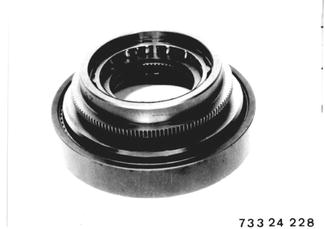 |
Press one-way clutch cage out of outer race carefully. Caution! Needles could jump out of cage. | 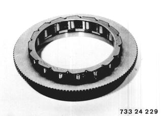 |
Installation: Place one-way clutch cage on the outer race and align. Press in one-way clutch cage against stop and then turn until metal edge engages in holding groove of outer race. | 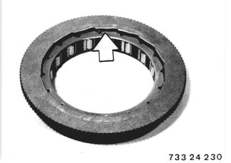 |
Use plate carrier (3) to turn one-way clutch outer race clockwise and mount race on inner race. | 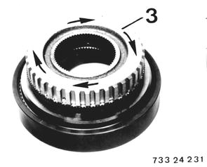 |
Clearance between one-way clutch inner race and outer race should be at least 0.1 mm (0.004´´). | 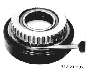 |
BMW 628csi - M635csi (M6)»24 - Transmission-automatic»24 23 022 - Plate clutches and brakes - replace