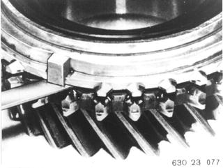
DISASSEMBLING/ASSEMBLING SYNCHRONIZATION - Transmission Removed - Remove input and output shafts 23 21 503. Disassemble output shaft (see 23 21 554). All synchromesh rings are identical and coated with molybdenum on inside surface. Synchromesh rings must be replaced when distance between synchromesh rind and clutch body is less than 1.0 mm (0.040´´). Measure in area of stops. This distance is 1.0 to 1.3 mm (0.040 to 0.051´´) for new synchromesh rings.  23 21 503 23 21 503 23 21 554 23 21 554
|  |
Check synchronization. Disassemble synchronizer. Spring (1), thrust pad (2) and ball (3). | 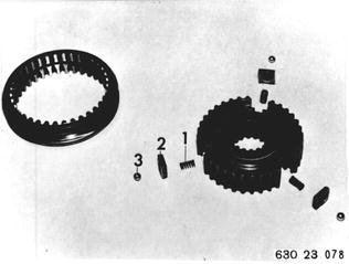 |
Installation: Install all springs, thrust pads and balls. Important: Curved surfaces of thrust pads (2) face operating sleeve. Insert synchronizer in sliding sleeve halfway. Push in balls far enough that synchronizer can be pushed into sliding sleeve. | 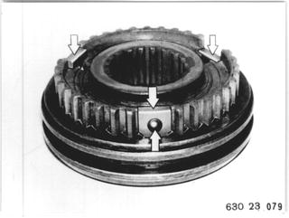 |
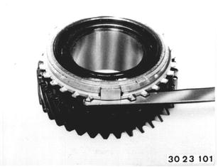
Vehicles after change point in 1982 DISASSEMBLING/ASSEMBLING ENTIRE SYNCHRONIZATION - Output Shaft Removed - Disassemble output shaft - see 23 21 554. Note: Only use molybdenum coated synchromesh rings for repairs. Check distance* between synchromesh ring and clutch. Measure in area of stops. Note: The synchromesh ring must be pressed on by screwing for measurements. Synchromesh rings must bear uniformly on the entire surface.  23 21 554 23 21 554 * See Specifications * See Specifications
|  |
Disassemble synchronization. Spring (1), thrust piece (2) and ball (3). Installation: Flat teeth of sliding sleeve must be aligned with thrust pieces. | 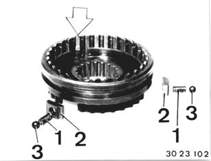 |
Install all springs, thrust pieces and balls. Important! Shouldered end of thrust pieces faces sliding sleeve. Place guide sleeve halfways in sliding sleeve. Push in balls far enough until guide sleeve can be pressed into sliding sleeve. | 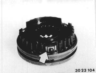 |
Modified Synchronization Since 5.85: Sliding sleeves with asymmetric splines. Thrust pieces (1), spring (2) and balls (3) in weaker version. Installation: Bevelled ends of thrust pieces face the sliding sleeve. For the 3rd/4th gear guide sleeve it is important to make sure that the bevelled end of sliding sleeve faces the long collar (4) of the guide sleeve or, for version with 3 grooves, faces the short collar of the guide sleeve. | 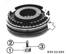 |
BMW 628csi - M635csi (M6)»23 - Transmission-manual»23 23 505 - Synchronization - disassembling ans assembling