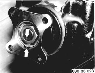
Vehicles before change point in 1982 REPLACING FINAL DRIVE FLANGE SHAFT SEAL (with removal/installation of drive pinion) Remove and install differential - 33 13 010. Mark installed position of input flange with a punch mark. Installation: Lock collar nut in groove of input flange with a new lockplate.  33 13 010 33 13 010
|  |
Check frictional torque with Special Tool 00 2 000 and note, e.g. 160 Ncm or (14 in.lbs.). | 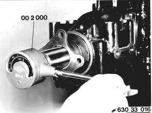 |
Counterhold input flange wit Special Tool 33 1 100 and unscrew collar nut. Installation: Torque values¹).  ¹) See Specifications ¹) See Specifications
|  |
Pull off input flange with Special Tool 31 1 150. Lift out shaft seal. Check shaft seal bearing surface on input flange. Replace input flange when bearing surface shows serious wear. | 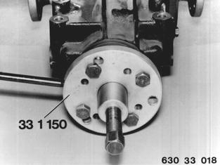 |
Installation: Install drive pinion with a new clamping sleeve. Pull front taper roller bearing on to drive pinion with Special Tools 23 1 300 and 23 2 150. Important: If taper roller bearing is heated in an oil bath, it must be given time to cool off completely prior to bearing adjustments, i.e. frictional torque tests. | 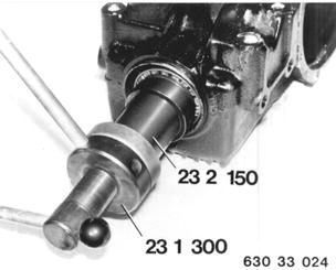 |
Lubricate sealing lip of shaft seal with final drive gear lube. Then knock in shaft seal flush with Special Tools 31 2 040 and 00 5 500. | 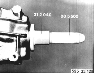 |
Press input flange on to input shaft with Special Tool 23 1 300. Tighten collar nut and check frictional torque. | 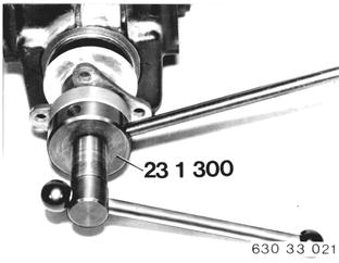 |
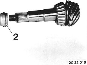
Adjust drive pinion bearing to frictional torque value found prior to disassembling and add 20 Ncm (2 in.lbs.) for new shaft seal. Important: Collar nut (1) must be tightened with at least 150 Nm (108 ft.lbs.). If this tightening torque value is not reached or the frictional torque value exceeded (see example), replace holding sleeve (2) and repeat measurement. Example: Frictional torque prior to disassembling ......160 Ncm (14 in.lbs.) New shaft seal................+ 20 Ncm (2 in.lbs.) Adjust drive pinion bearing to........................180 Ncm (16 in.lbs.) | 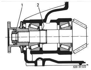 |
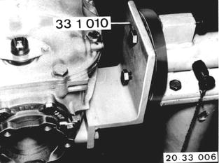
Vehicles after change point in 1982 RREPLACING SHAFT SEAL AND FINAL DRIVE INPUT FLANGE Remove final drive - see 33 10 010. Mount final drive on Special Tool 33 1 010. Drain oil. Take off case cover. Installation: Replace gasket. Tightening torque*. Add oil - oil volume*. See Service Information of Group 00 for approved oil.  33 10 010 33 10 010 * See Specifications * See Specifications
|  |
Remove lockplate. | 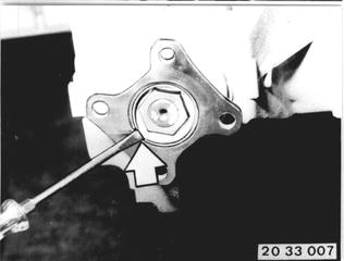 |
Press off drive flanges with a tire iron. | 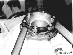 |
Punch mark both bearing caps. Remove both bearing caps. Important! Don´t mix up the bearing caps and spacers. If necessary, hold the spacers on bearing caps with pieces of wire. Installation: Tightening torque*.  * See Specifications * See Specifications
| 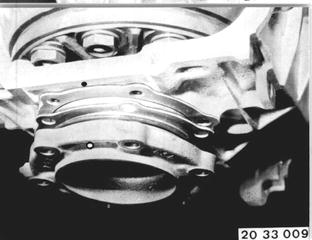 |
Differential case bearings and backlash are adjusted with shims (1). Check O-ring (2), replacing if necessary. | 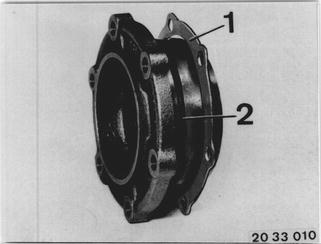 |
Remove differential assembly. Important! Don´t bend the pulse spider. | 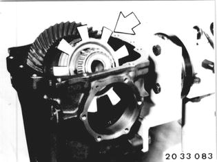 |
Measure friction torque with torque meter 00 2 000 and note the value. Important! The measured friction torque value + friction torque of new shaft seal (20 Ncm/2 in.lbs.) must be reached when assembling, but not exceeded. | 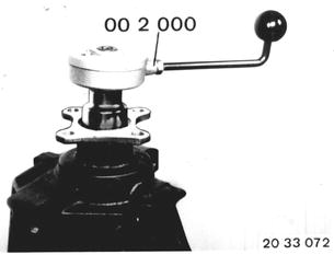 |
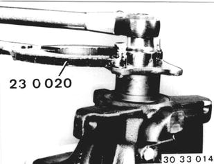
Hold the input flange with Special Tool 23 0 020. Unscrew the collar nut. Installation: Tightening torque*.  * See Specifications * See Specifications
|  |
Pull off the input flange with Special Tool 33 1 150. | 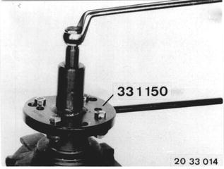 |
Pull out the shaft seal with Special Tool 00 5 010 and a thrust piece. | 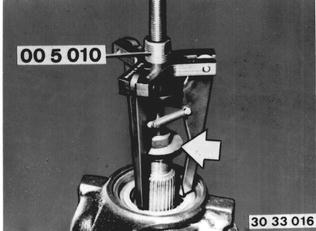 |
Dip the shaft seal in final drive gear lube and drive in the seal flush with Special Tool 33 1 270 or 33 1 190. | 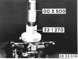 |
Press new input flange on to the input shaft with Special Tool 23 1 300, but do not tighten. The bushing does not have to be replaced when replacing the input flange. | 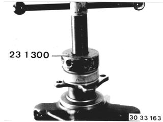 |
Tighten the input flange with the collar nut in steps, measuring the friction torque between steps. | 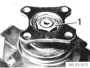 |
Adjust the drive pinion to the friction torque value measured prior to disassembling and add 20 Ncm (2 in.lbs.) for new shaft seal. Example: Measure torque................... 160 Ncm (14 in.lbs.) New shaft seal................... + 20 Ncm (2 in.lbs.) ________________________________________ Pinion bearing adjusted to..... 180 Ncm (16 in.lbs.) |  |
If the friction torque value (see example) is exceeded, replace bushing (2) and repeat the measuring procedures. This requires removing and installing drive pinion - see 33 12 551. Installation: Drive in a new lockplate with Special Tools 33 4 050 and 00 5 500.  33 12 551 33 12 551
|  |
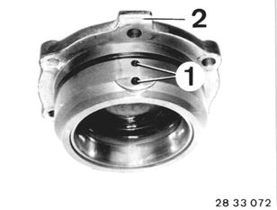
Installation: Install complete differential, checking for correct installation of bearing caps. The differential bores (1) always face up when the differential is installed correctly and this can be seen on the outside by way of tab (2). If applicable, check backlash and tooth contact pattern. See 33 12 551 for additional information.  33 12 551 33 12 551
|  |
BMW 628csi - M635csi (M6)»33 - Rear axle»33 11 011 - Shaft seal of final drive flange - replacing (with removal and installation of drive pinion)