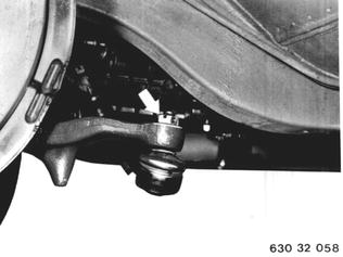
Vehicles before change point in 1982 REPLACING TIE ROD ARM Remove and install front wheel 36 10 300. Remove cotter pin and unscrew castle nut. Installation: Tightening torque¹). Lock castle nut with cotter pin. Check fron wheel alignment 32 00 034.  36 10 300 36 10 300 ¹) See Specifications ¹) See Specifications 32 00 034 32 00 034
|  |
Press outer tie rod off of tie rod arm with Special Tool 32 2 050. | 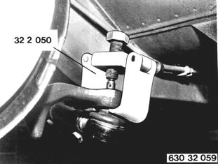 |
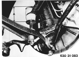
Unscrew bolts and press stabilizer off of control arm. Installation: Tightening torque¹) for control arm and distance (A) on pad for stabilizer must be maintained. Distance A = 60 mm (2.362´´) only for singlepiece rubber pad (also refer to 31 35 000).  ¹) See Specifications ¹) See Specifications 31 35 000 31 35 000
|  |
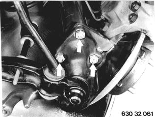
Remove lock wire and detach tie rod arm at spring strut. Installation: Tightening torque¹). Replace lock wire.  ¹) See Specifications ¹) See Specifications
|  |
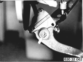
Remove cotter pin and unscrew castle nut. Installation: Tightening torque¹). Lock castle nut with cotter pin.  ¹) See Specifications ¹) See Specifications
|  |
Press tie rod arm off of control arm with Special Tool 00 7 500. | 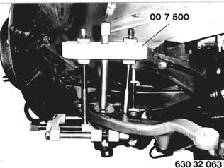 |
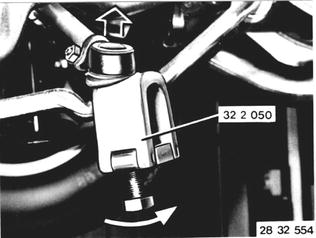
Vehicles after change point in 1982 REPLACING LEFT OR RIGHT TIE ROD ARM Remove front wheel - see 36 10 300. Remove cotter pin and unscrew castle nut. Press off ball joint with Special Tool 32 2 050. Installation: Replace self-locking nut on new type. Tightening torque*. Lock nut with cotter pin. Check front wheel alignment with optical tester - see 32 00 034.  36 10 300 36 10 300 * See Specifications of Gr. 32 * See Specifications of Gr. 32 32 00 034 32 00 034
|  |
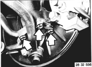
Unscrew bolts. Installation: Clean threads of tapped bores and bolts. Lock bolts with a bolt cement**. Tightening torque*.  ** Source: HWB ** Source: HWB * See Specifications of Gr. 32 * See Specifications of Gr. 32
|  |
Check for correct installed position. | 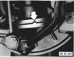 |
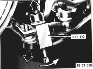
Remove cotter pin and unscrew castle nut on control arm and strut. Press off ball joints with Special Tool 31 1 110. Installation: Tightening torque*. Lock nut with cotter pin.  * See Specifications of Gr. 32 * See Specifications of Gr. 32
|  |