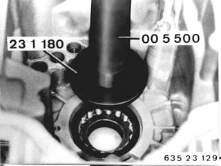
Vehicles after change point in 1982 REPLACING BEARINGS OF ALL TRANSMISSION SHAFTS - Transmission Removed - A) Input Shaft and Layshaft in Front Case Section: Remove front and rear case sections - see 23 11 006. Remove input and output shaft assembly - see 23 21 501. Dirve out bearing with Special Tools 23 1 180 and 00 5 500.  23 11 006 23 11 006 23 21 501 23 21 501
|  |
Heat front case section in area of bearing to about 80°C (175°F) with a hot air blower. Important! Install bearing with rollers facing the gear wheel set, driving in to fit tight with Special Tools 23 1 470 and 00 5 500 if necessary. | 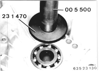 |
Layshaft: Drive out roller bearing with Special Tools 23 1 390 and 00 5 500. | 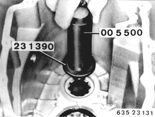 |
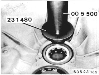
Heat front case section in area of bearing to about 80°C (175°F) with a hot air blower. Drive in roller bearing with Special Tools 23 1 480 and 00 5 500. Determine thickness of shim between bearing outer races in sealing cover - see 23 11 006.  23 11 006 23 11 006
|  |
Pull bearing inner race (1) off of the layshaft with Special Tool 00 7 500. Important! Bolt (2) must be screwed in the tapped bore to avoid damaging the threads. | 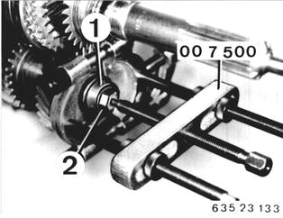 |
Heat new bearing inner race to about 80°C (175°F) with a hot air blower and install it on the layshaft. If necessary, drive it on to fit tight with Special Tool 23 1 160. | 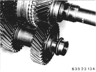 |
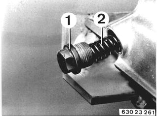
B) Output Shaft and Layshaft in Rear Case Section: Output Shaft: Unscrew bolt (1). Caution! Strong spring force. Remove spring (2). Installation: Install bolt with a bolt cement. Tightening torque*.  * See Specifications * See Specifications
|  |
Install Special Tool 23 1 250 for removal of the selector arm. | 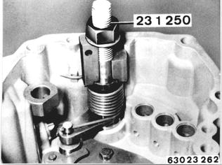 |
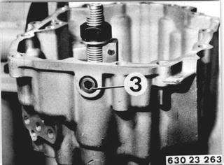
Remove hexagon socket bolt (3). Installation: Install bolt with a bolt cement. Tightening torque*.  * See Specifications * See Specifications
|  |
Remove selector arm from above. Important! Roller. | 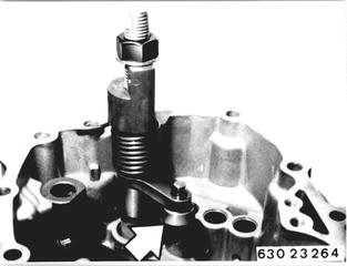 |
Installation: Install selector arm with Special Tool 23 1 250. Swing the selector arm out with the roller above locking lever (4). | 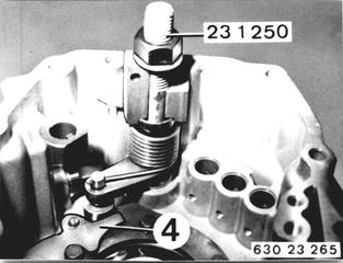 |
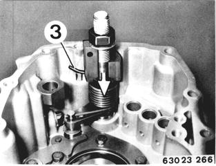
Position end of spring (3) above the high spot in installed position. Press down (don´t knock down) the selector arm in this position. Mount the selector arm with a hexagon socket bolt before removing the special tool. Tightening torque*. Install this hexagon socket bolt with a bolt cement.  * See Specifications * See Specifications
|  |
Remove bearing holder (5). Important! Do not unscrew bolt (6). Locking lever (7) remains on the bearing holder. | 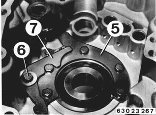 |
Installation: Check installed position of locking lever (7) and thrust pin (8). | 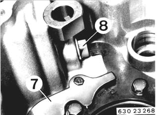 |
Lift out the radial oil seal. Drive out the grooved ball bearing with Special Tools 23 1 120 and 00 5 500. Important! Shim (D). | 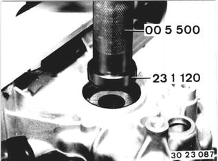 |
Determine thickness of shim (D). Measure distance (A). | 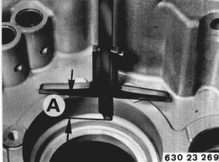 |
Measure distance (B). Example: ..A = 20.3 mm (0.799´´) - B = 20.0 mm (0.787´´) __________________ ..D = 0.3 mm (0.012´´) shim thickness | 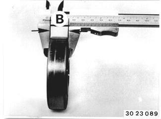 |
Heat rear case section in area of grooved ball bearing to about 80°C (175°F) with a hot air blower. Install shim (D). Install grooved ball bearing. If necessary, dirve in bearing against the stop with Special Tool 23 1 470. | 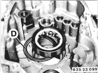 |
Pull bearing inner race off of the output shaft with Special Tools 23 1 100 and 00 7 500. The pulling hooks, Special Tools 23 1 100, must be modified to fit in the slots. | 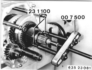 |
Heat ball bearing inner race to about 80°C (175°F) with a hot air blower and slide it onto the output shaft. Important! Turning lock - opening in bearing inner race must engage on the ball. Draw line (1) to make installation of the bearing race easier. | 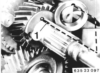 |
Layshaft: Guide Special Tool 23 1 280 into the bearing shell. | 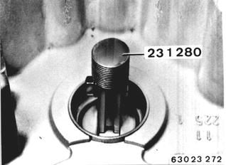 |
Apply Special Tool 33 4 020. Screw on Special Tool 23 1 300. Pull out the bearing shell. | 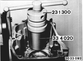 |
Drive in bearing shell with Special Tools 23 1 260 and 00 5 500. | 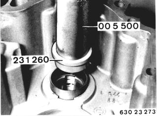 |
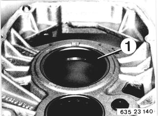
C) Output Shaft and Layshaft in Intermediate Case: Output Shaft: Check whether bearing outer race (1) can be used again. Replacement of the bearing outer race is only possible together with the complete intermediate case. The output shaft must be removed (see 23 21 552) to replace the roller bearing.  23 21 552 23 21 552
|  |
The reverse gear wheel shaft must be removed to remove the roller bearing of the layshaft. Press or knock out reverse gear wheel shaft (1). | 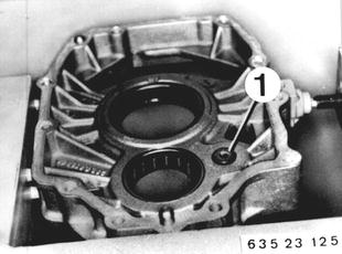 |
Drive roller bearing (2) out (and in) with Special Tools 23 1 130 and 00 5 500. The roller bearing must be flush. | 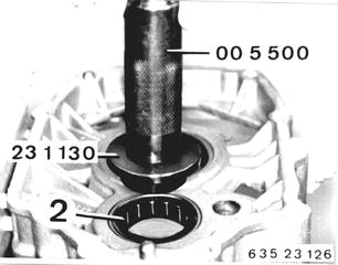 |
Mount reverse gear wheel shaft (1) on the rear case section with bolt (3). Note: Install this bolt with a bolt cement. Install needle bearing and reverse gear wheel. | 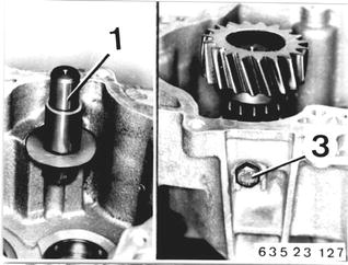 |
Take intermediate case off of Special Tool 23 0 030. Heat bore for the reverse gear wheel shaft to about 80°C (175°F) with a hot air blower. Place the intermediate case on the reverse gear wheel shaft (1) and align bores for case bolts. Unscrew bolt (3) and take the intermediate case off of the rear case section. | 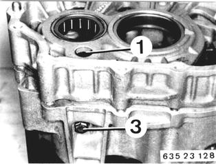 |