REMOVING AND INSTALLING CLUTCH Check clutch for wear before removing as follows. Liners are okay, if Special Tool 21 2 060 can be slid into opening of slave cylinder against stop. | 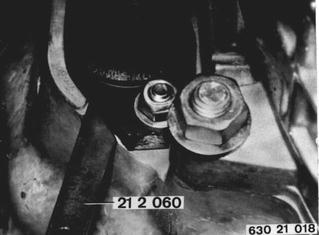 |
A gap (A) of 5 mm (0.197´´) between Special Tool 21 2 060 and slave cylinder indicates a worn drive plate. Replace drive plate. | 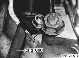 |
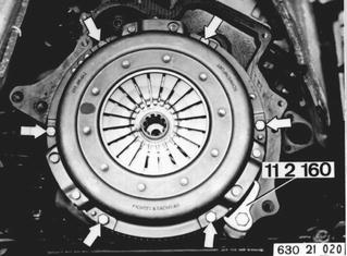
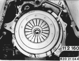
Remove clutch housing 21 11 000. Check out-of-true at ends of diaphragm springs¹). Hold flywheel with Special Tool 11 2 160. Loosen mounting bolts one after the other by 1 to 1 and 1/2 turns until clutch is without tension. Remove mounting bolts, clutch and drive plate. Important: Don´t throw or drop clutch. Improper handling could cause the tangential leaf springs holding clutch in axial direction to be bent off. The diaphragm springs would have the stroke, but because of the lame leaf springs the pressure ring would not lift high enough to release the drive plate.  21 11 000 21 11 000 ¹) See Specifications ¹) See Specifications
|  |
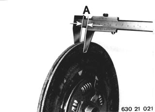
Check drive plate for wear (A)¹), cracks and torsional damper for tightness of spring elements. Installation: Note correct side of clutch.  ¹) See Specifications ¹) See Specifications
|  |
Installation: Check movement of needle bearing in crankshaft and replace if necessary. Check flywheel for cracks. Center drive plate in flywheel with Special Tool 21 2 100. | 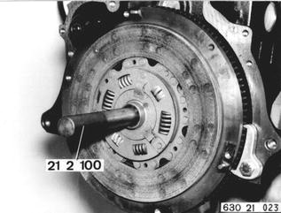 |
Inspect clutch for cracks, wear and burnt spots visually. Pressure surface must be level. | 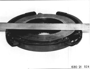 |
Check rivets for wear and tightness visually. Replace a clutch with losse or worn rivet heads. | 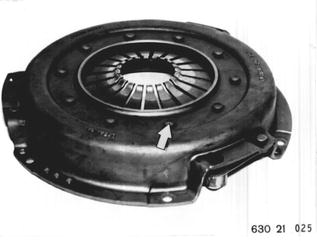 |
Place clutch over dowel pins. Tighten mounting bolts evenly one after the other to specified torque¹). Installation: Apply a light coat of Molykote Longterm 2 to splines of transmission input shaft.  ¹) See Specifications ¹) See Specifications
|  |
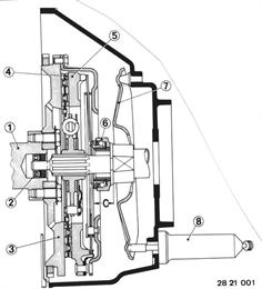
Clutch Assembly: 1 Crankshaft 2 Needle or grooved ball bearing 3 Flywheel 4 Drive plate BMW 630 CSi, 633 CSi: F & S 240 PSD 5 Pressure plate MF 240 BMW 630 CSi, 633 CSi: F & S No. 3082 007 303, green paint dot 6 Release BMW 630 CSi, 633 CSi: F & S No. 3151 035 201, C = 25.5 ± 0.25 mm (1.004 ± 0.010´´) 7 Release lever 8 Clutch slave cylinder | 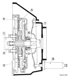 |
Vehicles after change point in 1982 REMOVING AND INSTALLING CLUTCH DISC Check clutch for wear without removing from car. If gauge 21 2 060 can be inserted in opening of slave cylinder against stop, liners are still good. | 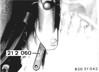 |
With a gap (A) of 5 mm (0.197") between gauge 21 2 060 and the slave cylinder, the drive plate is worn and must be replaced. | 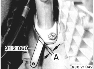 |
Remove transmission - see 23 00 022. Cars with 265/6 Transmission: Remove clutch housing - see 21 11 000. Check diaphragm spring tip deviation*. Hold flywheel with Special Tool 11 2 160. Loosen mounting bolts one after the other by 1 to 1 1/2 turns until the clutch is relaxed. Remove mounting bolts, clutch disc and drive plate. Important! Don't throw or let clutch fall. Improper handling could cause tangential leaf springs, holding clutch in direction of turning, to be bent off. Diaphragm spring would still initiate lift off, but because of weak leaf springs pressure ring would not lift off far enough and drive plate will not be cleared.  23 00 022 23 00 022 21 11 000 21 11 000 * See Specifications * See Specifications
|  |
Check drive plate of wear (A)*, cracks and the torsional damper for tight fit of spring elements. Installation: Note clutch end. Important! - Installation: Note transmission end mark on drive plate. |  |
Installation: Check grooved ball bearing in crankshaft for easy movement, replacing if necessary. Check flywheel for scoring. Center drive plate in flywheel with Special Tool 21 2 100. |  |
Visually inspect clutch for cracks, wear and burnt spots. Pressure contact surface must be level. |  |
Visually inspect rivets for wear and tight fit. Replace a clutch with loose or worn rivets. Important! Remove all corrosion inhibitor when installing a new clutch. |  |
Install clutch disc on dowel pins. Tighten mounting bolts uniformly in order to correct tightening torque*. Installation: Give keyways of transmission input shaft a light coat of Molykote Longterm 2.  * See Specifications * See Specifications
|  |
Clutch Assembly: 1 Crankshaft 2 Grooved ball bearing 3 Flywheel 4 Drive plate 240 mm (9.449") dia. 5 Pressure plate MF 240 Color codes* 6 Release C = 25 ± 0.25 mm (0.984 ± 0.010") 7 Release lever 8 Clutch slave cylindee  * See Specifications * See Specifications
|  |