INSTALLING RADIO WITH SPEAKERS; SHIELDING AND AUTOMATIC ANTENNA - 4 Speaker System - Disconnect battery ground. Install automatic antenna 65 22 000. Remove and install both rear seats 52 20 100. Installing Rear Speakers: (as from models 10/78) Loosen headrest trim screws at top left and right.  65 22 000 65 22 000 52 20 100 52 20 100
| 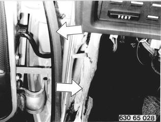 |
Detach trim at bottom and remove. | 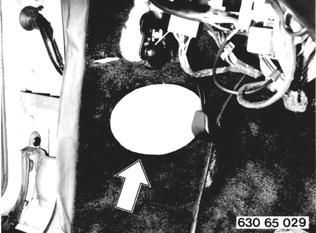 |
Lift tray bottom plate out of clips at front, rear and sides. Lift tray bottom plate and support from underneath. | 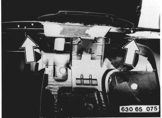 |
Route extra wires for rear speakers underneath tray bottom plate. Guide wires between lid hinges. | 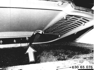 |
Push through tar paper cover and push wires with round male plug through. | 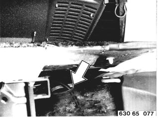 |
Connect wires on speakers. | 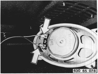 |
Mount speakers on lid with washers and knurled nuts. | 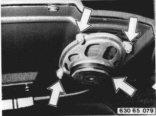 |
Make standard round male plug in trunk on left side above wheel house accessible. Connect both round male plugs and place plug connector in wire clamp. | 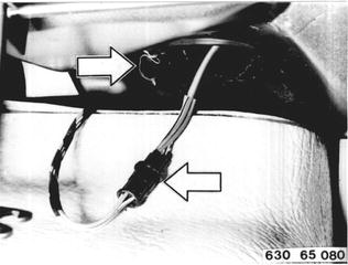 |
Installing Rear Speakers: (up to models 10/78) Open cover on hatrack. Feel out position of pre-punched opening and cut out. Push through cover located underneath. | 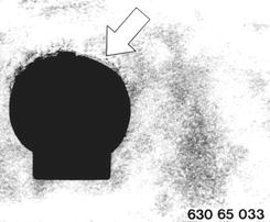 |
Lift trim slightly and insert metal nuts (1 ... 3) at holes provided for this purpose. | 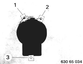 |
Mount shell for speaker with screws. Watch installed position. | 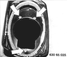 |
Bend open taps in trunk and pull back trim. | 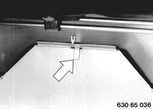 |
Route extra wires behind trim and fasten with adhesive tape. | 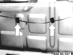 |
Connect extra wires with plug provided on left side and fasten with a wire clip. | 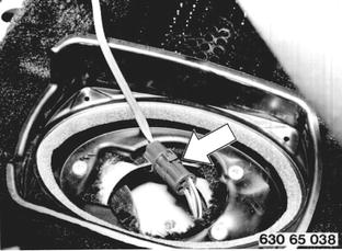 |
Place speaker in shell that connecting terminal faces forward and connect wires. | 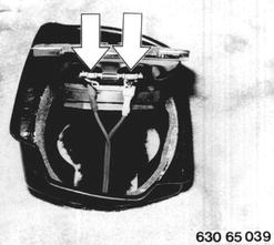 |
Install cover with curved surface facing up and fasten with screws. | 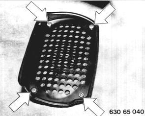 |
Only for Cars with Air Conditioner: Remove ashtray insert. Pull out cover for air conditioner toward rear from clips carefully. | 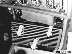 |
Remove hazard light switch and cigar lighter socket. Pull off plugs and wires. | 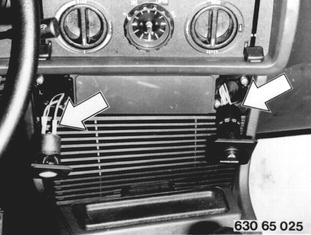 |
Remove plate (1) for radio. Loosen left and right screws. Remove radio carrier. | 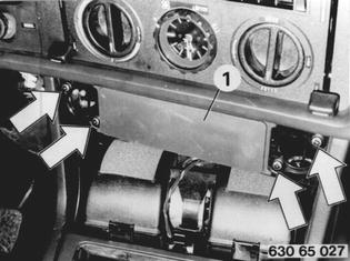 |
Important: There are two versions of radio carriers. 1st version (small opening) 2nd version (large opening) | 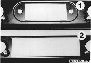 |
Make standard round male plug for rear speaker accessible. Connect round male plug with round plug of extra wire harness for front speakers. | 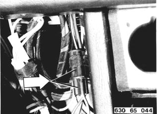 |
Connect both flat male plugs of extra lead on speaker balance control. Bevelled side of flat male plugs faces in. | 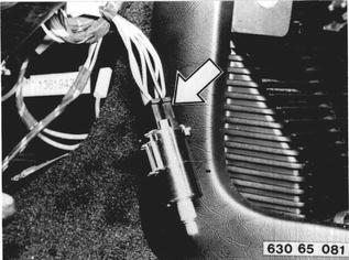 |
Route yellow/red extra wire to left door beam and blue/red extra wire to right door beam. Route both wire plugs (black and white) to place of radio installation. | 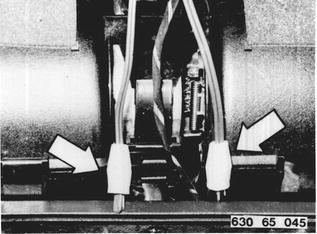 |
Installing Front Speakers: Pull off edge guard and door beam trim until opening for speaker is accessible. |  |
Cut out door beam trim elliptically. Important: Be careful of standard wires. |  |
Insert speaker wires in door beam from top to bottom through hole provided for this purpose. | 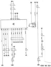 |
Connect wires on speakers. Mount plates and speakers with screws (1 ... 4). | 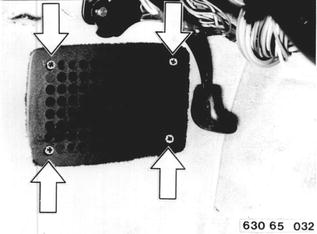 |
Installing Stereo Radio with Cassette Player: Bavaria CR: Open glove box. Mount electronic interference suppressor together with impact switch. Route wire to impact switch. Bend interference suppressor down to prevent rattling. | 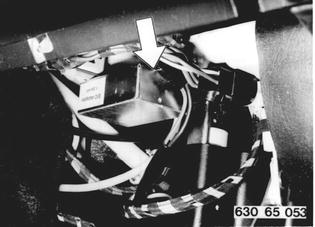 |
If radio carrier has a small opening, it must be replaced by one with a large opening. Remove clips (1) from standard radio carrier and mount them on new carrier. | 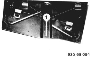 |
Install radio in radio carrier and mount with bracket (1). Center bracket. Tightening torque: 40 Ncm (3.5 in.lbs.). | 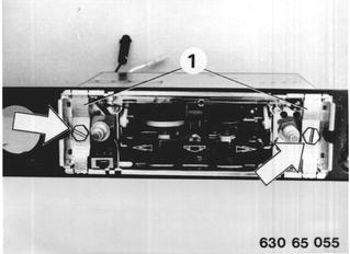 |
Press plate (2) into clips. Insert operating lever (3) in arrest. | 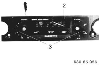 |
Install knobs (4) on radio. | 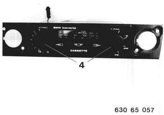 |
Mount bracket (1) on radio carrier and radio. | 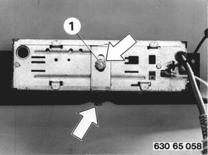 |
Connect antenna wire (1) and electronic interference suppressor (2) on radio. | 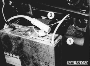 |
Connect white control wire (1) of automatic antenna on radio. | 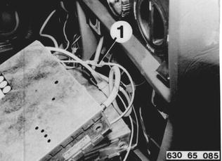 |
Connect flying fuse (3) with plug terminal (4). Connect ground wire (5) and speaker wire (6) on radio. Connect battery ground and check function of radio. | 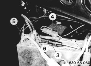 |
Install radio with radio carrier and tighten. | 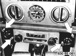 |
Trim antenna according to instructions supplied with radio. | 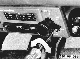 |
Cut out pre-punched opening in instrument panel trim down to sheet metal. | 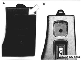 |
Puncture hole (1) and drill 4 mm (0.157´´) dia. hole (2). Distance A = 10 mm (0.394´´). | 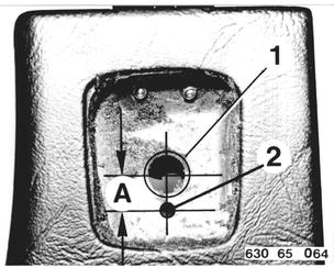 |
Insert speaker balance control in arrest and mount plate (1) with nut. Install knob. Install all removed parts. Paste trim. | 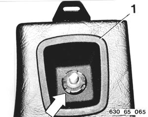 |
Installing Interference Suppressors: Install ground wire between engine hood and spray wall on right side. | 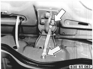 |
Install ground wire between valve cover and firewall. | 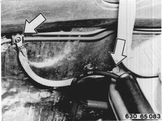 |
Take off distributor cap. Push shielded cap (1) on distributor cap and install distributor cap. Fasten ground wire (2) from shielded cap with screw for vacuum box. |  |
BMW 628csi - M635csi (M6)»65 - Radio and accessories»65 11 025 - Radio with speakers, shielding and automatic antenna (4 speaker set) - installing