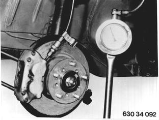
Vehicles before change point in 1982 CHECKING FUNCTION OF BRAKE PRESSURE REGULATOR Remove and install front wheel - 36 10 300. Remove and install rear wheel - 36 10 300. Connect a pressure gauge in front axle brake circuit. Bleed this high pressure gauge.  36 10 300 36 10 300
|  |
||||||||||||
Connect a second high pressure gauge to rear wheel brake bleeder. Bleed high pressure gauge. | 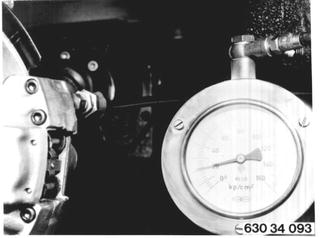 |
||||||||||||
Floor brake pedal at least 5 times. Hold down brake pedal with a pedal prop. At pressures up to 20 bar (280 psi) both high pressure gauges must show same reading. At pressures above 20 bar (280 psi) pressure of rear wheel brake cylinder must drop according to diagram. A = Inlet pressure B = Outlet pressure C = Dispersion range Replace brake pressure regulator, if measured values are off of specifications. | 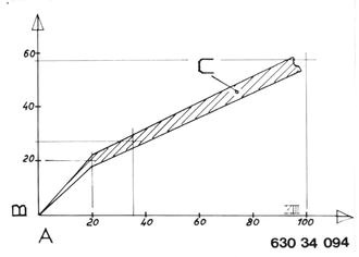 |
||||||||||||
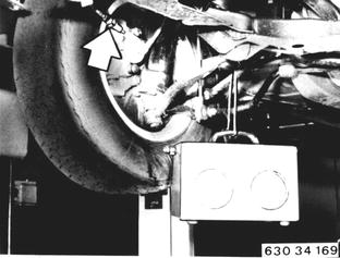
Vehicles after change point in 1982 CHECKING FUNCTION OF BRAKE FORCE REGULATOR (Not on M 6) Remove rear wheels 36 10 300. Connect one high pressure gauge in 1st brake circuit at front right. Bleed high pressure gauge.  36 10 300 36 10 300
|  |
||||||||||||
Connect second high pressure gauge on bleeder of 1st brake circuit at rear left. Bleed high pressure gauge. | 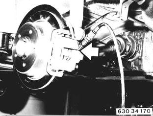 |
||||||||||||
Operate brake pedal firmly at least 5 times. Hold brake pedal down with a pedal prop. Both pressure gauges should show same value up to pressure of 40 bar (569 psi). Pressure of rear wheel cylinder must be reduced as shown in diagram beginning with 40 bar (569 psi). | 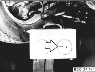 |
||||||||||||
A = Inlet pressure (bar) B = Outlet pressure (bar) C = Switching pressure (bar) Example: Inlet pressure (= front wheel brake pressure)
Outlet pressure (= rear wheel brake pressure)
If necessary, take mean value of three measurements. If measured values deviate from nominal values, replace brake force regulator of pertinent brake circuit. Repeat measurement on 2nd brake circuit. | 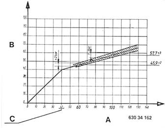 |