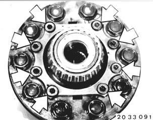
Vehicles after change point in 1982 DISASSEBLING/ASSEMBLING LIMITED SLIP DIFFERENTIAL - Final Drive Removed - Remove limited slip differential - see "Replacing Limited Slip Differential" - 33 14 520. Unscrew case cover mounting bolts. Take off case cover.  33 14 520 33 14 520
|  |
Turn case upside down to let parts slide out. Installed Order: (1) case cover, (2) thrust washer, (3) disphragm spring, (4) stepped washer, (5) spacer, (6) diaphragm spring, (7) outer plate, (8) inner plate, (9) thrust ring, (10) differential side gear, (11) differential gears with differential shafts, (12) differential case. | 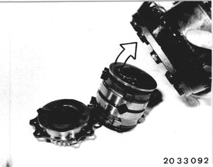 |
Check all parts for wear, e.g. molybdenum coat, splines, etc... Installation: Lubricate all parts with approved final drive oil before assembling. | 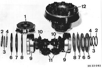 |
Install following parts in correct installed order to measure the pre-load. Spacer (5), outer plates (7), inner plates (8), thrust rings (9) , differential side gears (10) and differential gears with differential shafts (11). Measure distance A from case edge to outer plate, e.g. A = 19.5 mm (0.768´´). | 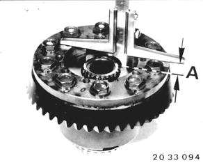 |
Measure distance B on cover, e.b. B = 14.4 mm (0.567´´). | 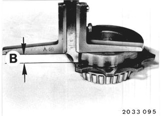 |
Place both diaphragm spring curved surfaces together. Measure distance C on diaphragm springs, e.g. C = 4.8 mm (0.189´´). | 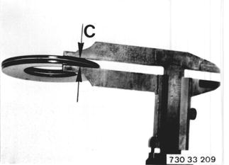 |
An installed clearance of 0.1 to 0.4 mm (0.004 to 0.016´´) is required to prevent pressing the diaphragm springs flat. Example: B (cover)............................... 14.4 mm (0.567´´) C (diaphragm springs).............. 4.8 mm (0.189´´) A (case)................................. 19.5 mm (0.768´´) Sum of B + C .........................19.2 mm (0.756´´) Installed clearance D...............0.3 mm (0.012´´) Correct any deviation in installed clearance D by installing outer plates of correct thickness. | 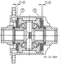 |
Remove all parts from case and insert with the additional parts, thrust washers (2), diaphragm springs (3) and stepped washers (4). Mount and press on case cover (12) firmly (don´t bolt). The pre-load of small diaphragm springs (3) should produce an uniform gap all around (check with feeler gauge blade). If there is no clearance between cover and case, check diaphragm springs (3), thrust washers (2) and stepped washers (4). | 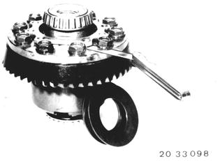 |
Installed Order: Thrust washer (2) with oil pockets facing case (down). Diaphragm spring (3) with inside curved surface facing differential shaft (up). Stepped washer (4) with smooth side facing diaphragm spring (down) and tab engaging in guide in case. | 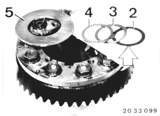 |
Install spacer (5), diaphragm spring (6) with inside curved surface facing differential shaft and outer plate (7) with four tabs. Install molybdenum coated inner plate (8). | 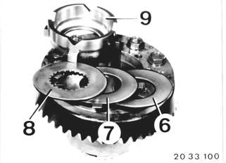 |
Install thrust ring (9) and dirfferential side gear (10) by turning in guides or spline of inner plate. Install differential gears with shafts (11), second differential side gear (10) and thrust ring (9). | 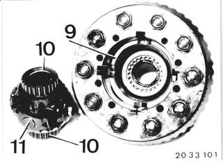 |
Install molybdenum coated inner plate (8) and outer plate (7). Insert diaphragm spring (6) with inside curved surface facing differential shaft (down). | 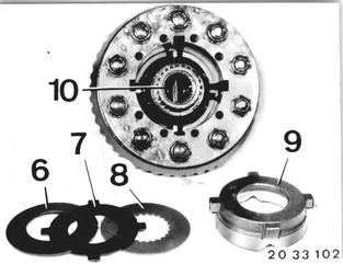 |
Insert thrust washer (2) with oil pockets facing cover, diaphragm spring (3) with inside curved surface facing out and stepped washer (4) with smooth side facing diaphragm spring and with tab in case cover groove in case with grease. | 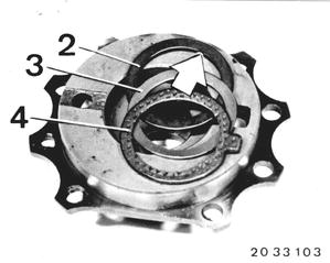 |
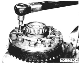
Mount case cover with washers (don´t let stepped washer slide out of groove). Install bolts with Loctite No. 270 and tighten cover uniformly. Installation: Tightening torque*.  * See Specifications * See Specifications
|  |
Check slip torque* of differential lock by holding one and driving other differential side gear. Make up tool locally for this purpose by, for example, welding a nut on a drive flange which is no longer required. | 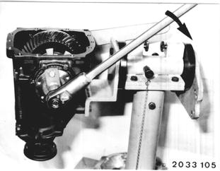 |
BMW 628csi - M635csi (M6)»33 - Rear axle»33 14 593 - Limited slip differential - disassemble and assemble