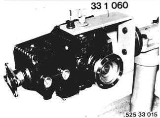
Vehicles before change point in 1982 REPLACING LOCKING DIFFERENTIAL Remove and install final drive - 33 10 010. Drain oil. Mount final drive on Special Tool 33 1 060 after unscrewing oil drain plug (1) for this purpose.  33 10 010 33 10 010
|  |
Check total frictional torque prior to disassembling, using Special Tool 00 2 000, and note, e.g. 180 Ncm (16 in.lbs.) | 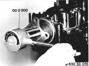 |
Remove left and right drive flanges. Pull off drive flange with Special Tool 33 1 250. | 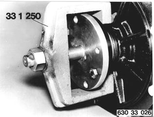 |
Installation: Prior to installation of drive flange, place wire snap ring (1) in groove of differential case that both of its ends are recessed in groove. This will prevent lateral bending of snap ring. Press in drive flange by hand and turn slightly, until wire snap ring can be heard to engage. Replace stretched snap rings. | 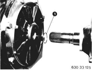 |
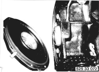
Take off cover and remove locking differential. Installation: Check O-ring, replacing if necessary. Torque values¹).  ¹) See Specifications ¹) See Specifications
|  |
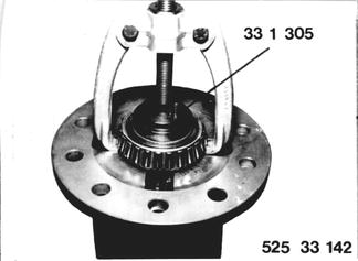
Detach ring gear from locking differential. Pull off taper roller bearings through openings in differential case with a standard puller and Special Tool 33 1 305. Installation: Install ring gear and taper roller bearings cold. Clean threads. Install bolts with Loctite¹). Torque values¹). Check taper roller bearings, replacing if necessary.  ¹) See Specifications ¹) See Specifications
|  |
Install new locking differential with ring gear. Tighten cover mounting bolts uniformly to 15 ... 25 Nm (11 ... 18 ft.lbs.). Check total frictional torque with Special Tool 00 2 000. It must be same as frictional torque value noted prior to disassembling, but not exceeding same. Frictional Torque Too High: use thinner shim. Frictional Torque Too Low: use thicker shim. |  |
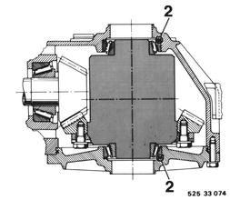
Adjust backlash and tooth contact pattern with shims (2). Change shims (2) from one side to other until backlash¹) and tooth pattern are correct. Never alter total thickness of shims.  ¹) See Specifications ¹) See Specifications
|  |
If tooth contact pattern is not correct, adjustment must be corrected with shim X (see "General Information on Tooth Contact Patterns" on page 33-12/10). Important: Check frictional torque before unscrewing collar nut (1). Always replace holding sleeve (2). Adjust pinion bearing to frictional torque value measured prior to disassembling. Collar nut must be tightened to at least 150 Nm (108 ft.lbs.). If this value is not reached or exceeded, replace holding sleeve (2) and repeat measurements. | 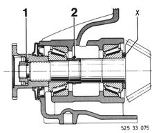 |