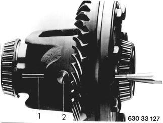
Vehicles before change point in 1982 REPLACING DIFFFERENTIAL GEARS A) One Piece Differential: Remove and install differential - 33 13 010. Drive out key (1) and differential gear shaft (2).  33 13 010 33 13 010
|  |
Turn out both differential gears with drive flange. | 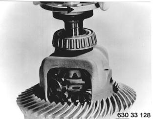 |
Remove differential side gears with diaphragm springs and shim. Installation: Check parts, replacing if necessary. | 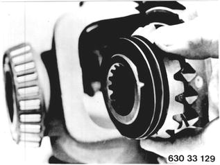 |
Install both differential side gears with diaphragm springs and shims. Center differential side gears with drive flanges. | 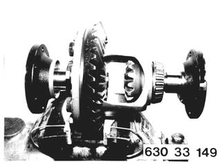 |
Install one M 10 x 25 bolt (1) with nut (2), Special Tool 33 1 430 and washer (3) having outside dia. of 35 mm (1.378´´) and inside dia. of 10 mm (0.394´´). Press differential side gears so far apart, that drive flanges can still be turned. | 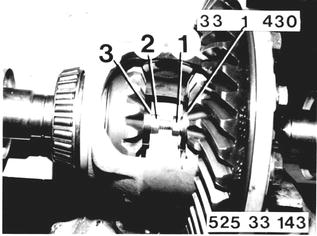 |
Install differential gears. Mount Special Tool 33 1 100 on drive flange and turn in differential gears. Remove bolt and washers. Drive in differential gear shaft. Lock differential gear shaft with a pin. | 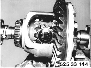 |
Mount Special Tool 33 1 430 on inside of differential side gear with gauge bolt and tighten. | 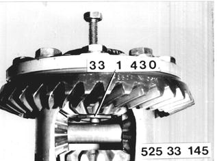 |
Mount dial gauge holder with gauge. Set dial gauge to 0 (zero) with preload. | 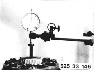 |
Loosen gauge bolt until diaphragm spring is relaxed. Read dial gauge. A play of 0.03 to 0.10 mm (0.0012 to 0.0040´´) is required to make sure that diaphragm springs are not pressed flat. Lowest value would be ideal. Shims are available in steps of 0.05mm (0.002´´). Procedures are identical for opposite side. | 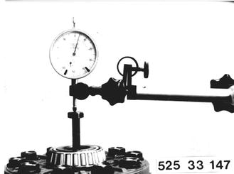 |
Installation: Install determined shims (2) and diaphragm spring (1). Concave side of diaphragm spring (1) faces differential side gear. | 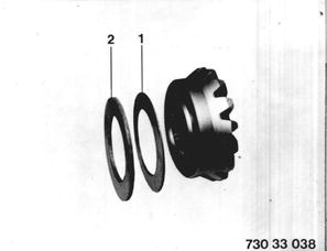 |
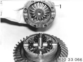
B) Two Piece Differential: Remove and install differential - 33 13 010. Take off upper section (1) of differential. Installation: Tighten bolts to 22 + 2 Nm (16 + 1.5 ft.lbs.).  33 13 010 33 13 010
|  |
Remove differential gears and shafts (2 and 3). | 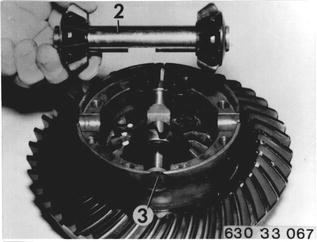 |
Remove differential side gears (4) with diaphragm springs (5) and shims (6). | 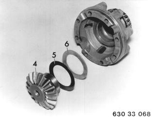 |
Installation: Install one differential side gear and one differential gear shaft with two differential gears. Do not install diaphragm spring and shim. Assemble differential. Mount dial gauge holder 33 1 240 with dial gauge. Press differential side gear firmly against differential gears with a screwdriver and set dial gauge to zero. |  |
Press differential side gear against differential case and read dial gauge, e.g. 2.90 mm (0.114´´). | 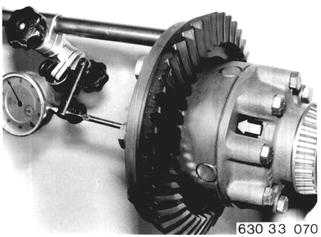 |
The thickness (X) of shims and diaphragm springs will be determined by subtracting 0.05 to 0.10 mm (0.002 to 0.004´´) from above value. Example: 2.90 mm (0.114´´) - 0.05mm (0.002´´) ______________ 2.85 mm (0.112´´) The deduction of 0.05 to 0.10 mm (0.002 to 0.004´´) from distance (X) is necessary, to prevent pressing the diaphragm springs flat. | 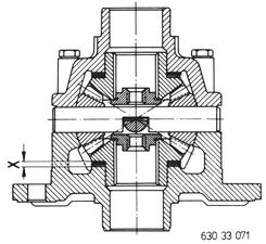 |
Use same procedures for opposite side. Install shim (A) and diaphragm spring (B). Concave side of diaphragm spring (B) faces differential side gear. | 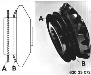 |
Install both drive flanges. Hold one drive flange and turn the other. Slip torque should be 15 to 25 Nm (11 to 18 ft.lbs.). | 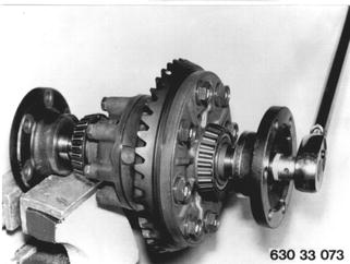 |
General Information On Locking Differential: A locking differential has the following advantages. a) Slipping of a wheel bouncing over rough road surfaces is reduced to a minimum. b) Slipping of one wheel on road surfaces with different traction values while moving off or driving is prevented. c) Wheel on inside of curve does not slip while driving fast in curves. d) Wheels will not slip on wet roads when driving at high speed. e) No danger of skidding when driving fast on road surfaces with different traction values. | 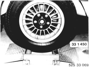 |
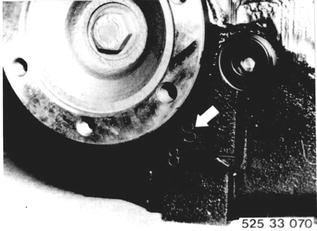
Function Test Installed In Car: a) Level shop floor. b) Drive left wheel of car on to Special Tool 33 1 450. c) Release parking brake fully. d) Engage 1st gear and accelerate engine. e) Locking differential function correctly, if car can be driven from Special Tool 33 1 450. Locking differentials with the designation "S"¹) are fitted with molybdenum-lined inner plates.  ¹) See Specifications ¹) See Specifications
|  |