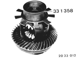
Vehicles after change point in 1982 REPLACING DIFFERENTIAL GEARS - Differential Removed - See "Replacing Drive Pinion with Ring Gear" in 33 12 551 for information on removing the differential. Press off the pulse spider. Installation: Press on pulse spider with Special Tool 33 1 358.  33 12 551 33 12 551
|  |
Remove ring gear (cold). Important! If bearings also have to be replaced, install ring gear only after determination of the friction torque - see "Replacing Bearings for Differential Case" in 33 11 724.  * See Specifications * See Specifications
| |
Installation: Clean threads thoroughly (tapper). Heat ring gear to max. 100°C (212°F) and check temperature with a thermochrome pencil. Install ring gear with two locally manufactured staybolts as guides. | 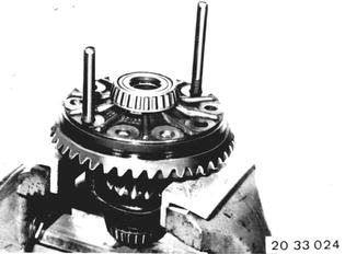 |
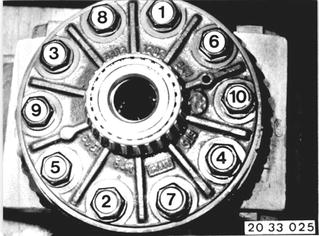
Install bolts with Loctite Nr. 270 and tighten in order of 1 through 10. Tightening torque*. Tighten bolts to torque angle*.  * See Specifications * See Specifications
|  |
Press out differential shaft from countersunk end with Special Tool 33 1 470. A = Pressing out direction E = Pressing in direction | 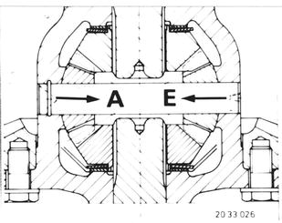 |
Tunr out differential bevel gears with drive flange. Remove differential side gears with diaphragm springs and shims. | 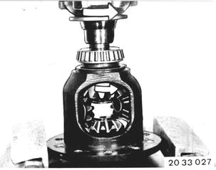 |
Install both differential side gears with diaphragm springs (1) and shims (2). Curved surface of diaphragm springs (1) faces differential case. Center differential side gears with drive flange. | 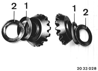 |
Insert Special Tool 33 1 306 on one side. Screw in Special Tool 33 1 441 with Special Tool 33 1 430. Tighten special tool bolt to spread differential side gears so far apart, that the drive flange can just barely be turned. | 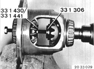 |
Install differential bevel gears exactly opposite each other. Move differential gears to installed position by turning drive flange. Remove special tools. | 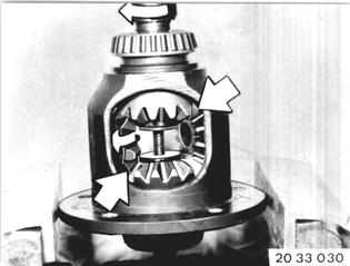 |
Procedures with Hydraulic Press: Check that circlip (1) is in correct installed position. Slide in feed mandrel from side without a circlip. | 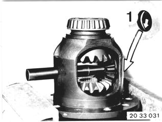 |
Place differential shaft with large opening on the feed mandrel and press in. The pressing-in force will increase strongly, when the circlip has engaged. Caution! Stop the pressing-in step as soon as the force increases - danger of shearing off the circlip. Do not push back the differential shaft after installation. | 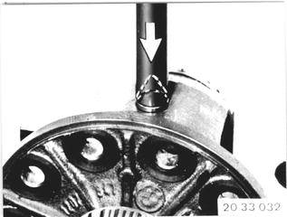 |
Measuring Pre-load of Diaphragm Springs: Install Special Tools 33 1 441 and 33 1 431. Tighten bolt by hand. | 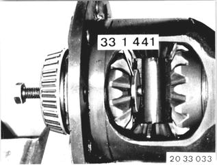 |
Mount dial gage with holder, consisting of Special Tools 33 1 420, 00 2 505 and 00 2 506, on differential case. Set dial gage to zero with pre-load on the blocked shaft gear. | 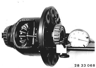 |
Tighten spindle until diaphragm springs are pressed flat. Rear dial gage. Loosen spindle. Thrun shaft gear and measure again at several points. A clearance of 0.03 to 0.1 mm (0.0012 to 0.0039´´) is required to avoid pressing the diaphragm springs flat. The lower value would be ideal. Repeat measurements on opposite shaft gear. | 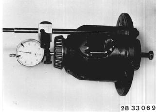 |
Excessive Clearance: Install thicker shim. Insufficient Clearance: Install thinner shim. Shims (2) are available in 0.05 mm (0.0020´´) thickness steps. The opposite end is determined in the same manner. | 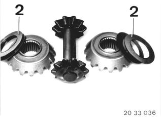 |
Install shims (2) of determined thickness and diaphragm springs (1). Inside curved surfaces of diaphragm springs (1) face differential case. |  |
Procedures with Special Tool 00 8 500: Check that circlip (1) is in correct installed position. Slide in Special Tool 33 1 470 from side without circlip. |  |
Place differential gear shaft with large opening on special tool and press in until 1 to 2 cm (3/8 to 3/4´´) of shaft is visible. |  |
Apply Special Tool 00 8 500 on differential cage and pull in differential gear shaft with a torque breaking wrench. Torque Adjusting Value: 18 mm spindle dia. = 22 Nm (16 ft.lbs.). 20 mm spindle dia. = 22 Nm (16 ft.lbs.). Important! Lubricate center on differential gear shaft with oil before application of the special tool. Differential gear shaft must no longer be pushed back after installation. Make sure that last fourth of torque (from about 17 N/ 12 ft.lbs.) is applied at constant speed (not suddenly). | 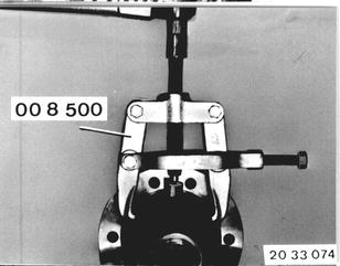 |
Measuring Pre-load of Diaphragm Springs: Install Special Tool 33 1 441 and a spindle. Tighten spindle by hand. |  |
Mount holder with dial gage. Set dial gage to zero with pre-load. |  |
Tighten spindle unit diaphragm springs are pressed flat. Read dial gage. Loosen spindle. Turn shaft gear and repeat measurement at several points. A clearance of 0.03 to 0.1 mm (0.0012 to 0.0039´´) is required to prevent pressing the diaphragm springs flat. Lowest value would be ideal. Repeat measurements on opposite shaft gear. |  |
Excessive Clearance: Install thicker shim. Insufficient Clearance: Install thinner shim. Shims (2) are available in 0.05 mm (0.0020´´) thickness steps. Determine opposite end in same manner. |  |
Install shims (2) of determined thickness and diaphragm springs (1). Inside curved surfaces of diaphragm springs (1) face the differential case. |  |