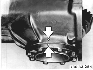
Vehicles after change point in 1982 REPLACING DRIVE PINION WITH RING GEAR - Final Drive Removed - Remove final drive - see 33 10 010 in repair manual of pertinent model series beginning with 1985 models. Remove complete differential. Important! Mark bearing covers - do not mix up washers.  33 10 010 33 10 010
|  |
Lift out lockplate. Unscrew nut (1), counterholding with Special Tool 23 0 020. | 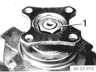 |
Pull off input flange with Special Tool 33 1 150. The specified friction torque is given with the new drive pinion bearing, so that the friction torque of the old bearing does not have to be measured. | 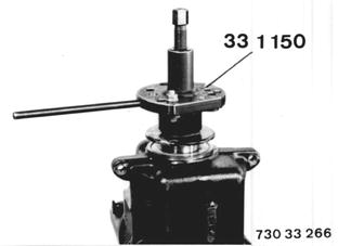 |
Press out drive pinion. Caution! Be careful not to damage threads. | 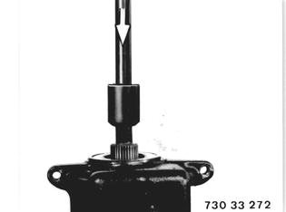 |
Pull out front bearing outer race with Special Tool 33 1 350. 1 Spreader 2 Front bearing outer race 3 Puller bell housing 4 Pressure bolt | 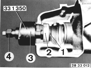 |
Pull out rear bearing outer race with Special Tool 33 1 360. Puller consists of: Puller head................ 33 1 361 Threaded spindle.......33 1 362 Bearing bridge........... 33 1 356 Pressure nut.............. 33 1 363 Important! Shim (X) is located underneath the rear bearing outer race. It will be needed again for pinion/ring gear adjustments. | 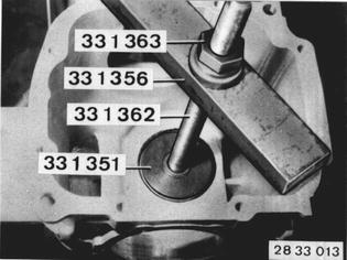 |
Install old shim (X) in front of the rear bearing outer race. Pull in bearing outer races with Special Tool 33 1 360. Puller consists of: Puller disc for front outer race.. 33 1 373 Puller disc for rear outer race....33 1 365 Threaded spindle..................... 33 1 362 Pressure nut............................. 33 1 363 Nut........................................... 33 1 354 | 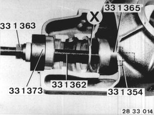 |
Press tapered roller bearing on to drive pinion with Special Tool 33 1 330. | 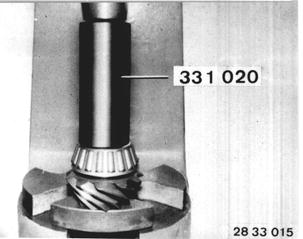 |
Important! Drive pinions and ring gears are matched in special machines for optimum smooth running. The pair code (P) is electrically inscribed in the drive pinion and ring gear. Never install a ring gear and drive pinion with different pair codes together. | 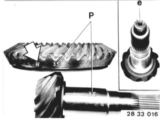 |
The number inscribed with + or - is the deviation from basic distance C in 1/100ths of millimeters and is required to determine the thickness of shims. e+ is added to C. e- is subtracted from C. H indicates type of teeth. H = Gleason. | 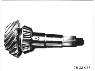 |
To determine the thickness of shim (X), install drive pinion with new tapered roller bearings, but without bush. | 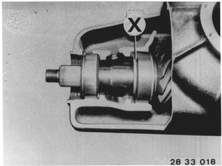 |
Place drive pinion in rear bearing outer race. Apply Special Tool 33 1 341 on drive pinion and pull front taper roller bearing on to drive pinion with Special Tools 23 1 300 and 33 1 342. | 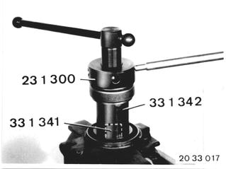 |
Attach input flange. Adjust friction torque of drive pinion roller bearing to 250 Ncm (22 in.lbs.) by tightening collar nut. | 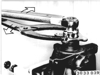 |
Mount dial gage in Special Tool 33 1 411. Place Special Tool 33 1 411 with dial gage on Special Tool 33 1 412 and set dial gage to 0 (zero) with pre-load. | 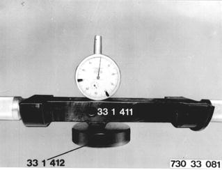 |
Place Special Tool 33 1 412 on drive pinion. Place Special Tool 33 1 411 in case. Determine value Y. Basic distance C = 18.50 mm (0.728´´) Gage thickness B = 17.50 mm (0.689´´) | 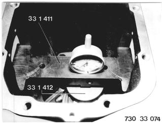 |
Example I C.......................... 18.50 mm (0.728´´) e- .........................- 0.30 mm (0.011´´) _____________________________ C target ................18.20 mm (0.717´´) _____________________________ Value Y measured on dial gage...........0.60 mm (0.023´´) Sum B..................17.50 mm (0.689´´) Sum Y.................+ 0.60 mm (0.024´´) ____________________________ C actual...............18.10 mm (0.713´´) ____________________________ C target................18.20 mm (0.717´´) C actual.............- 18.10 mm (0.713´´) ____________________________ a............................0.10 mm (0.004´´) ____________________________ Gage A..................4.14 mm (0.163´´) -a...........................0.10 mm (0.004´´) ____________________________ Shim X...................4.04mm (0.159´´) If target C is larger than actual C, "a" is subtractecd (-) from thickness of shim X. Example II C..........................18.50 mm (0.728´´) e+.......................+ 0.10 mm (0.004´´) _____________________________ C target................18.60 mm (0.732´´) _____________________________ Value Y measured on dial gage............1.20 mm (0.047´´) Sum B...................17.50 mm (0.689´´) Sum Y..................+ 1.20 mm (0.047´´) _____________________________ C actual ................18.70 mm (0.736´´) _____________________________ C actual.................18.70 mm (0.736´´) C nominal.............- 18.60 mm (0.732´´) _____________________________ a..............................0.10 mm (0.004´´) _____________________________ Gage A....................4.10 mm (0.161´´) +a............................0.10 mm (0.004´´) _____________________________ Shim X.....................4.20 mm (0.165´´) If target C is smaller than actual C, "a" is added (+) to thickness of shim X. The permissible tolerance for distance (X) results from the graduation of 0.01 to 0.03 mm (0.0004 to 0.0012´´) depending on shim thickness. | 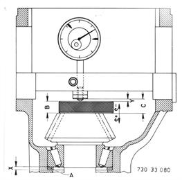 |
Remove drive pinion and rear bearing outer race. Press in shim (X) of determined thickness and bearing outer race. |  |
Important! Do not install the drive pinion at this point, since it is first necessary to measure and adjust the friction torque of the new differential case bearing. | 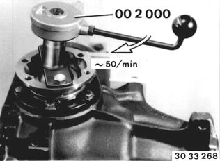 |
Press pulse spider off of differential case. Caution! Be careful not to bend the pulse spider. | 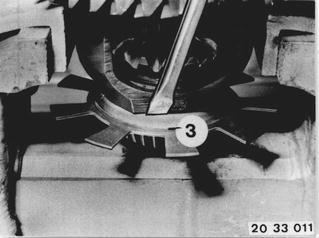 |
Installation: Press on pulse spider with Special Tool 33 1 304. | 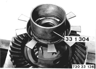 |
Remove ring gear (cold). Installation: Clean threads thoroughly (with a tapper). Heat ring gear to max. 100°C (212°F), checking temperature with a thermochrome pencil. Mount ring gear with two locally made staybolts as guides. | 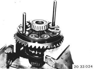 |
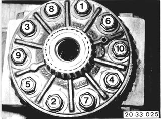
Install new bolts with Loctite No. 270 and tighten in order of (1 ... 10). Tightening torque*. Tighten bolts to torque angle*.  * See Specifications * See Specifications
|  |
Pull off tapered roller bearing on differential case with Special Tool 33 1 300. | 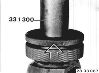 |
Installation: Press on new tapered roller bearing cold with Special Tool 33 1 003. | 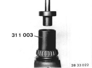 |
Lift shaft seals out of both bearing caps. Installation: Dip new shaft seals in final drive gear lube. Drive in shaft seals against stop with Special Tools 33 1 230 and 00 5 500. | 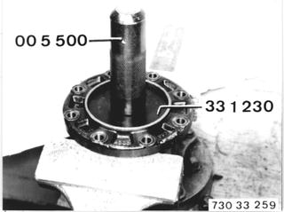 |
Prress out bearing outer race with Special Tools 33 1 350 and 33 1 351. Important! Special Tool 33 1 351 must engage in the bearing outer race. | 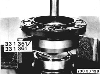 |
Installation: Press in new bearing outer races with Special Tool 33 1 365 or 33 1 368. | 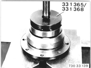 |
The following 12 steps can only be omitted, if the differential case bearings were not replaced. Install dirfferential case with new ring gear and new bearings. Lubricate bearings thoroughly with approved final drive gear lube** and let them drip dry.  ** See Service Information of Gr. 00 ** See Service Information of Gr. 00
| 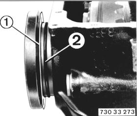 |
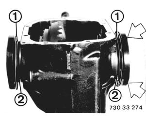
Install side bearing caps marked with belonging shims (1), but at first without O-rings (2). Tighten bearing cover bolts on the side opposite the ring gear uniformly. Tightening torque*.  * See Specifications * See Specifications
|  |
- Friction Torque of Differential Case Bearings - Only tighten the bolts of the second bearing cap uniformly as long as the differential can still be turned. | 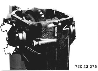 |
Apply an output flange on the side tightened to the tightening torque and measure the friction torque with a locally made clamp with a welded nut and friction torque meter 00 2 000. Turn friction torque meter at speed of approx. 50 rpm. | 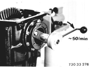 |
The friction torque value given with the new differential bearing set +20 Ncm (2 in.lbs.) for each new shaft seal in which a shaft runs while measuring, should be reached, but must not be exceeded. | 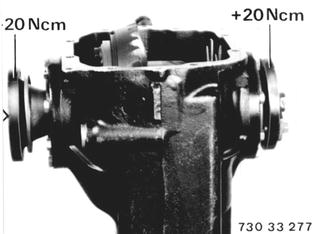 |
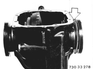
If the given friction torque is not reached, even though both bearing caps are tightened to the correct tigthening torque*, install a thinner shim opposite the ring gear and repeat the measuring procedures.  * See Specifications * See Specifications
|  |
If the friction torque is reached, even though the second bearing cap has not yet been tightened to the correct tightening torque*, a thicker shim must be used on the ring gear end and the measuring procedures repeated.  * See Specifications * See Specifications
| 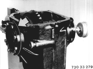 |
To make finding the shim thickness easier, the distance between the shim and case can be measured with a feeler gage blade and added to the thickness of the used shim. | 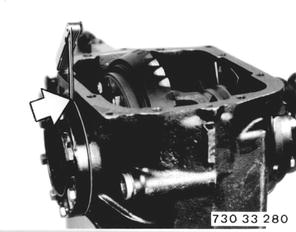 |
Example: Second bearing cap not tightened (bolts screwed on uniformly). Friction torque value specified in the bearing set package: 180 Ncm (15 in.lbs.). 1 Output flange inserted New shaft seal: 20 Ncm (2 in.lbs.). Measured friction torque: 200 Ncm (17 in.lbs.). Gap measured with feeler gage blade......................... 0.20 mm (0.008´´) Used shim thickness:................... 1.40 mm (0.055´´) _________________________________________ Install shim of thickness:.............. 1.60 mm (0.063´´) and repeat measuring procedures. | 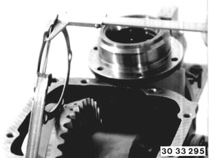 |
Remove differential to install the drive pinion. (If the differential case bearings had not been replaced, it is allowed to continue from this point). Important! Do not mix up side covers and shims. | 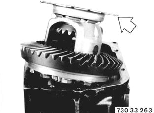 |
Install drive pinion with a new sleeve (2). Drive in shaft seal and bolt input flange. | 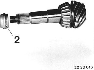 |
Important! Tighten collar nut (1) in steps and measure the friction torque between steps with Special Tool 00 2 000. Only tighten the collar nut enough, that the friction torque given with the new tapered roller bearing plus 20 Ncm (2 in.lbs.) for the new shaft seal is reached. The friction torque should be reached, but not exceeded. If the friction torque is exceeded, sleeve (2) will have to be replaced and the measuring procedures repeated. | 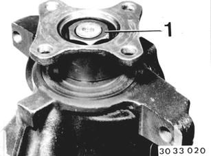 |
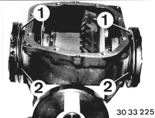
Install differential. Install side covers according to marks with corresponding washers (1) and new O-rings (2). Tightening torque*.  * See Specifications * See Specifications
|  |
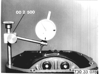
- Backlash/Tooth Contact Pattern Adjustment - Mount Special Tool 00 2 500 and measure backlash* with dial gage. Important! The tooth contact pattern is always most important for a perfectly adjusted pinion/ring gear set.  * See Specifications * See Specifications
|  |
To check the tooth contact pattern, coat the ring gear teeth with printer´s ink, turn in both directions several times and stop ring gear suddenly with a piece of hard wood. | 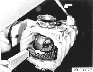 |
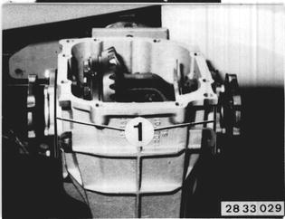
Correct backlash* and tooth contact pattern by changing the thickness of both shims (1). If backlash is excessive, use a thinner shim on the ring gear end. If backlash is too small, use a thicker shim on the ring gear end. An axial displacement of the ring gear by 0.01 mm (0.0004´´) will cause a change in backlash of 0.0076 mm (0.0003´´). Important! The total thickness of both shims must not be changed. If a thinner or thicker shim is required to correct the tooth contact pattern, the total thickness must be corrected with the second shim, since otherwise the friction torque of bearings would be changed again.  * See Specifications * See Specifications
|  |
GENERAL INFORMATION ON TOOTH PATTERN ADJUSTMENTS Gleason Teeth A Correct tooth pattern without load. A1 Loads will shift tooth contact pattern outward slightly. Moving the ring gear will mainly change the backlash, but will also displace the contact pattern in longitudinal direction of the teeth. Moving the drive pinion will displace the contact pattern in favor of tooth height, but the backlash will be altered just very slightly. Here are the four basically incorrect contact patterns, which usually occur in combination. Knowing these patterns will facilitate making adjustments. 1. High, narrow contact pattern (tip contact) on ring gear. Move drive pinion toward ring gear shaft and perhaps correct backlash by backing ring gear off of drive pinion. 2. Deep, narrow contact pattern (root contact) on ring gear. Move drive pinion away from ring gear shaft and perhaps correct backlash by moving in ring gear. 3. Short contact pattern on small tooth end (toe contact) of ring gear. Move ring gear away from drive pinion. Maybe move pinion closer to ring gear shaft. 4. Short contact pattern on large tooth end (heel contact) of ring gear. Move ring gear toward drive pinion. Perhaps back drive pinion away from ring gear shaft. | 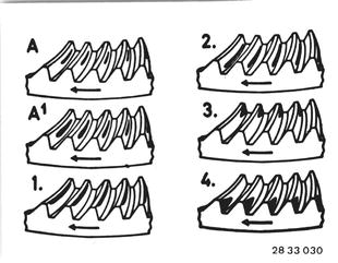 |
Adjustment of contact pattern | 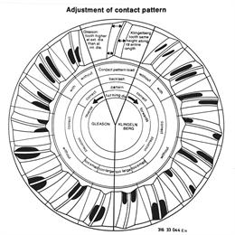 |