Vehicles after change point in 1982 REPLACING RADIAL OIL SEAL FOR SECTOR SHAFT AND STEERING WORM AND SEALING INTERMEDIATE COVER - POWER STEERING GEAR REMOVED - Absolute cleanliness is essential for work on steering gears! Power steering gear code no.: 8052 955 206. | |
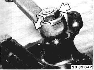
Bend open lockplate and unscrew nut. Installation: Replace lock plate. Tightening torque*. Lock nut.  * See Specifications * See Specifications
|  |
Pull off steering drop arm with Special Tool 32 2 000. | 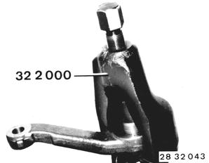 |
Installation: Check installed position (marks on steering drop arm and shaft). | 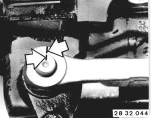 |
Mark position of cover to case. Unscrew nut (1). Unscrew bolts (2) and lift off cover by turning adjusting screw (3). | 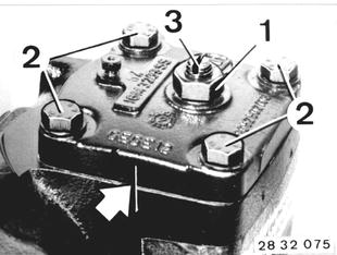 |
Pull sector shaft out of case. | 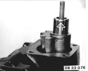 |
Pull off cap (1). Unscrew bolts (2). | 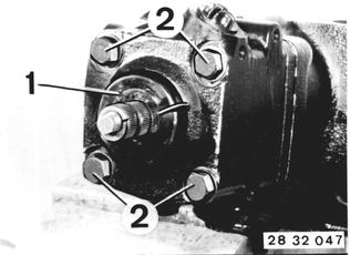 |
Mark position of valve housing (1) and intermediate cover (2) to case. Take off valve housing (1). | 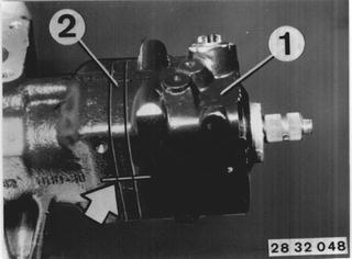 |
Remove angular ball bearing (1). Pull out worm with piston. | 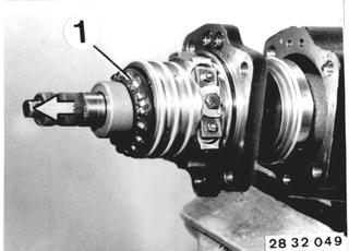 |
Set up piston and remove worm by turning clockwise. Caution! 23 loose balls. | 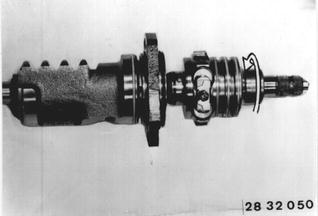 |
Lift out circlip. Press out outer radial oil seal (1) and inner radial oil seal (2). | 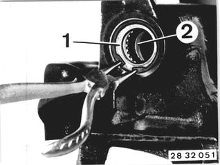 |
Lubricate lips of radial oil seals with grease. Insert support ring (3) and press in radial oil seal (2) with Special Tool 32 1 060 that lip of seal faces inside of case. Press in radial oil seal (1) with Special Tool 32 1 070 (lip of seal facing inside of case) and insert circlip (4). | 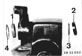 |
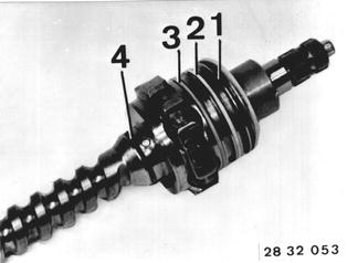
Replace seals (1 ... 4) and O-rings located behind. Coat seals with hydraulic fluid*.  * See Service Information of Gr. 00 * See Service Information of Gr. 00
|  |
Replace seal (1) and O-ring (2) located behind. Coat seal with hydraulic fluid*.  * See Service Information of Gr. 00 * See Service Information of Gr. 00
| 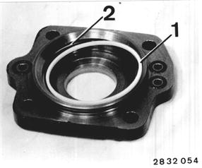 |
Replace O-rings (1 ... 3) on both sides and O-ring (4). | 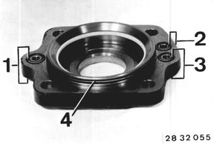 |
Place bearing ring (1) and axle bearing (2) in intermediate cover (with a little grease to hold). | 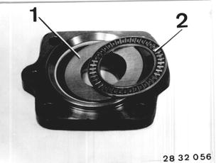 |
Place intermediate cover on worm head, being careful not to damage seal of worm. | 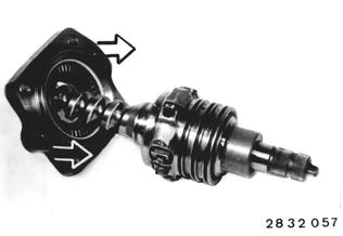 |
Pull off cap (1) and remove circulating pipe (2). | 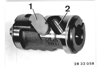 |
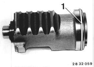
Replace seal (1) and O-ring located behind. Coat seal with hydraulic fluid*.  * See Service Information of Gr. 00 * See Service Information of Gr. 00
|  |
Slide worm head into piston. A = approx. 6 cm (2.362´´). Insert 16 balls into thread grooves of worm through bore (1) while turning the worm, until balls have been forwarded to bore (2). | 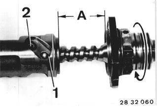 |
Place 7 balls in circulating pipe (both outside balls with a little grease) and insert circulating pipe in piston. | 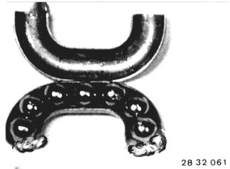 |
Insert O-ring (1) and seal (2) in cap. Press cap into piston. | 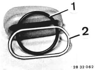 |
Place O-ring (1) in steering case. | 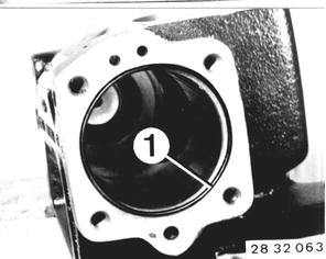 |
Push piston into steering case, being carful not to damage seal of piston. | 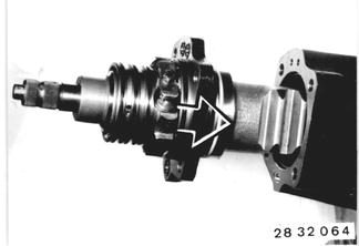 |
Install new radial oil seal (lip lubricated with grease) in valve housing with Special Tool 32 1 080 (lip faces inside of case). | 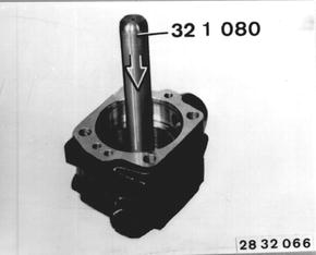 |
Insert ball bearing (1) and Special Tool 32 3 054. | 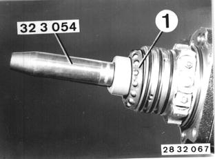 |
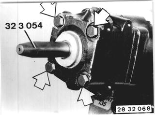
Push valve housing over seals of worm head carfully and tighten bolts. Tightening torque*. Remove Special Tool 32 3 054.  * See Specifications * See Specifications
|  |
Turn steering to one of the end positions. Turn back about 2 turns until marks on spindle and case are aligned = straight ahead position. | 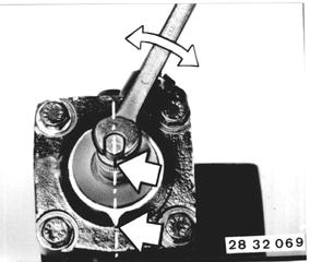 |
Pack cap with grease and press on to spindle - marks on spindle, cap and case must be aligned. | 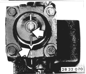 |
Slide in sector shaft (mark on face at right angle to piston axis) carefully that radial oil seals are not damaged. | 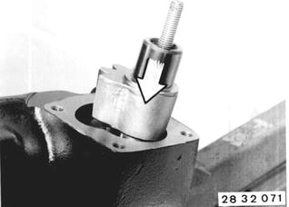 |
Replace O-ring in cover. Position cover on case by turning the adjusting screw anticlockwise. | 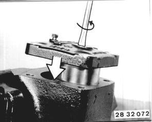 |
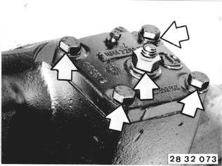
Bolt cover. Tightening torque*. Screw on lock nut finger tight (because of sealing surface on cover).  * See Specifications * See Specifications
|  |
Adjusting Pressure Point: Mount Special Tool 32 1 000 on spindle and apply torque meter 00 2 000. Measure friction torque about 1/2 turn before end stop. Move steering gear to straight ahead position. Turn adjusting screw until friction torque is 40 to 50 Ncm (3.5 to 4.3 in.lbs.) higher than the previously measured friction torque value while "passing" the pressure point. Total friction torque must not exceed 160 Ncm (14 in.lbs.). Tighten lock nut to 25 Nm (18 ft.lbs.). Recheck friction torque. Attach steering drop arm. Check operation of steering gear after installation | 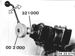 |
BMW 628csi - M635csi (M6)»32 - Steering and wheel alignment»32 13 631 - Radial oil seal for sector shaft and steering worm - replace (and sealing intermediate cover)