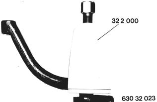
Vehicles before change point in 1982 DISASSEMBLING(ASSEMBLING POWER STEERING GEAR Important: Power steering gears may only be repaired in exceptional cases. Normally the steering gear would be replaced. Remove and install power steering gear 32 13 060. Steering Drop Arm: Open lockplate. Unscrew nut. Pull off steering drop arm with Special Tool 32 2 000. Installation: Tightening torque¹).  32 13 060 32 13 060 ¹) See Specifications ¹) See Specifications
|  |
Check steering drop arm. Distance A = 112.5 ± 0.5 mm (4.429 ± 0.020´´´) Distance B = 26 mm (1.024´´) | 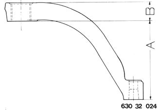 |
Installation: Marks on steering drop arm and sector shaft must align with each other. | 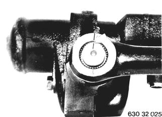 |
Pressure Point Cover: Mark position of cover to box with punch (K). Unscrew nut (1), holding bolt (2). Unscrew cover mounting bolts. Installation: Tightening torque¹).  ¹) See Specifications ¹) See Specifications
| 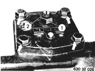 |
Lift cover by turning adjusting screw clockwise. Installation: Check O-ring (3) in cover, replacing if necessary. Position cover correctly before tightening the cover´s adjusting screw. | 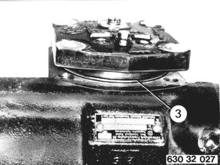 |
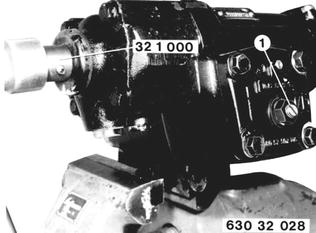
Installation: Find middle position of worm shaft by taking half of the total number of turns. Turn worm shaft anticlockwise by 1 turn. After installation of Special Tools 32 1 000 and 00 2 000 turn shaft clockwise past pressure point and read friction torque value¹). To adjust, turn worm shaft anticlockwise by 1 turn. Turn adjusting screw (1) clockwise until specified friction torque value¹) is reached when passing pressure point.  ¹) See Specifications ¹) See Specifications
|  |
Sector Shaft: Pull out sector shaft in middle position. Installation: Fill spline with hot bearing grease Slide in sector shaft carefully to prevent damage to radial oil seals. | 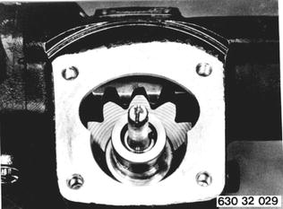 |
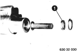
Check axial play¹) of adjusting screw and correct with a thicker washer (1) if necessary. Adjusting screw must turn easily without restriction.  ¹) See Specifications ¹) See Specifications
|  |
Remove circlip (1) and radial oil seal (2). Pull off needle bearing (3). Knock out needle bearing (4) with support disc (5) and oil seal (6). Installation: Sealing lips of oil seals (2 and 6) face inside of housing. | 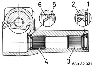 |
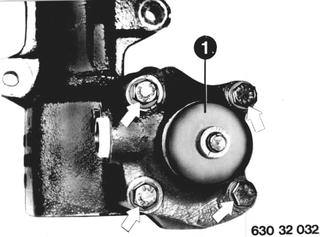
Valve Housing: Pull off cap (1) and detach valve housing. Installation: Tightening torque¹). Wrap cellophane tape around spline to avoid damage to radial oil seal.  ¹) See Specifications ¹) See Specifications
|  |
Remove ball bearings. Installation: Check oil seals (1 ... 4), replacing if necessary. | 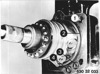 |
Only applicable when replacing needle bearings: Press off bearing race (1). Scrape off double needle cage (2). Installation: Position bearing race (1) and needle cage (2) to each other without play. For this purpose the needle cage (2) is available in four different sizes. | 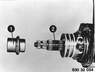 |
Intermediate Cover: Pull worm with intermediate cover and piston out of housing. Installation: Check oil seals (1 ... 4), replacing if necessary. | 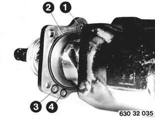 |
Turn worm out of piston. Important: Balls! Remove intermediate cover. Take off circlip (1) and remove ball recirculating tube (2). | 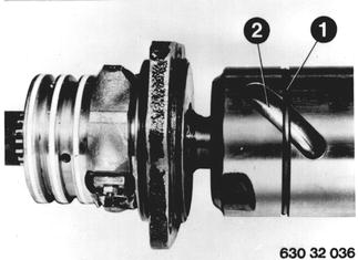 |
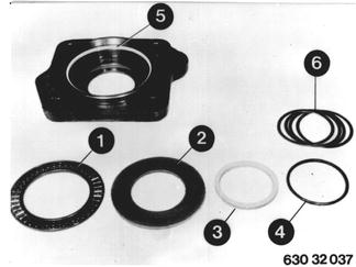
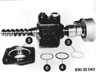
Check needle cage (1), bearing disc (2), grooved ring (3), O-ring (4) and teflon ring (5). Installation: Shims 0 ... 4 (6) are optional. Select number of shims to give a preload to sealing lip of grooved ring (3). Don´t exceed max. specified friction torque value¹).  ¹) See Specifications ¹) See Specifications
|  |
Installation: Mount valve housing without radial oil seal, worm head without teflon seals, intermediate cover without O-ring and grooved ring with ball bearing, needle cage (1) and support disc (2) to valve housing. | 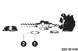 |
Mount valve housing with intermediate cover to steering gear. Tighten bolts uniformly to specified torque¹). Adjust friction torque¹) for worm bearings with support disc (2). Support disc (2) is available in different sizes in steps of 1/100 mm.  ¹) See Specifications ¹) See Specifications
| 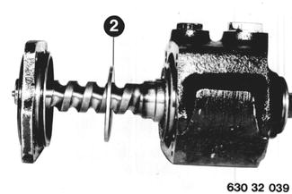 |
Check preload of teflon ring in intermediate cover. Place support disc and needle cage in intermediate cover. Install O-ring (1) and teflon ring (2) in groove. A = 1.7 mm (0.067´´). | 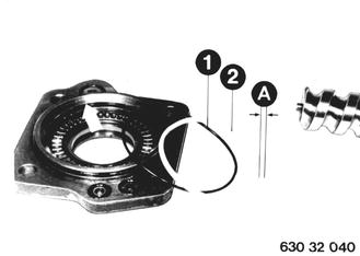 |
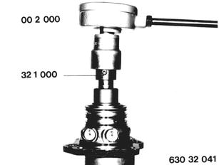
Install worm shaft in intermediate cover. Mount Special Tool 32 1 000 and measure specified friction torque¹) in vertical position with Special Tool 00 2 000. Install a thicker teflon ring, if friction torque value is insufficient. Important: Don´t clamp intermediate cover.  ¹) See Specifications ¹) See Specifications
|  |
Teflon Rings, Worm Head, Pistons: Lift teflon rings (1 ... 4) out of worm head and piston with a feeler gage blade. Remove O-ring (5). Installation: Replace removed rings. | 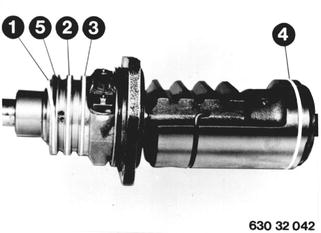 |
Checking and Adjusting Worm Head´s Total Friction Torque: Teflon rings installed in worm head and radial seal in valve housing. Teflon ring (5) installed in intermediate cover and friction torque measured. Install O-ring (4) and grooved ring (3), sealing lip facing piston end, with the previously removed shims (6). Install worm head in valve housing. Mount intermediate cover with valve housing on steering gear and measure friction torque. Use shims (6) to adjust preload of grooved ring (3) 10 Ncm (1 in.lbs.) higher than the previously measured friction torque value in the intermediate cover. Installation: Tightening torque¹).  ¹) See Specifications ¹) See Specifications
|  |
Piston and Worm: Important: Don´t remove valve piston (1). If removed, hydraulic center point adjusted exactly over steering spindle and torsion bar would no longer be correct. Check adjustment of steering limit valve. A = 107 _ 0.20 mm (4.212 _ 0.008´´). | 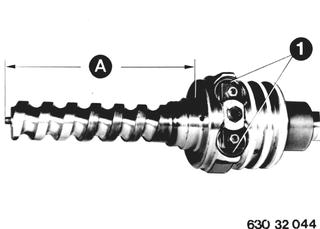 |
Steering Limit Valve (15) | 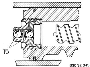 |
Steering limit valve must open shortly before reaching steering lock. Adjust stop screw (2) that steering limit valve will open 2 mm (0.080´´) in front of tie rod arm stop. | 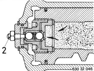 |
Guide worm into piston. A = approx. 6 cm (2.362´´). Insert 16 balls through front bore. Turn worm toward inside while inserting balls. | 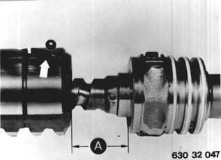 |
Place 7 balls in recirculating tube. Hold both outer balls in position with grease. | 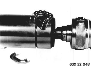 |
Secure ball recirculating tube with circlip. | 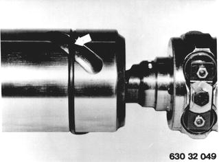 |
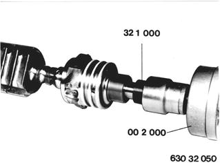
Unscrew worm by about 3 1/2 turns. Check friction torque¹) horizontally over a range of at least 90° with Special Tools 00 2 000 and 32 1 000. Friction torque is given by ball diameter. Important: Only use balls of same diameter, i.e. same tolerance group. Remove worm after adjusting friction torque. Install intermediate cover and assemble worm with piston. Important: Never unscrew worm by more than 3 1/2 turns to prevent balls from falling into piston bore.  ¹) See Specifications ¹) See Specifications
|  |
BMW 628csi - M635csi (M6)»32 - Steering and wheel alignment»32 13 103 - Power stearing gear - disassembling and assembling