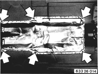
REMOVING AND INSTALLING CENTER BEARING Remove exhaust assembly 18 00 020. 1980 Models: Detach heat shield.  18 00 020 18 00 020
|  |
 |
|
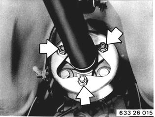
To prevent stress in Giubo coupling and therefore vibration and drumming noise, use Special Tool 26 1 011 for removal and installation of propeller shaft. Unscrew bolts. Installation: Use stop nuts only once. | 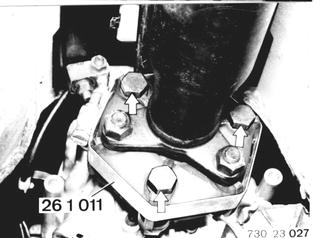 |
Tighten Special Tool 26 1 011 until bolts can be removed by hand. | 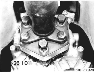 |
Remove heat shield. | 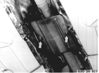 |
Detach center bearing. Installation: Preload center bearing forward by distance (A) = about 2 mm (0.080´´). | 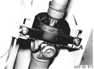 |
Bend down propeller shaft and pull out of centering pin on transmission. | 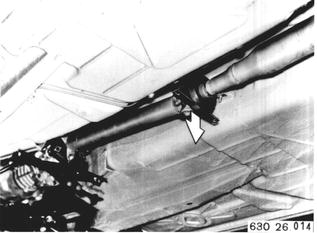 |
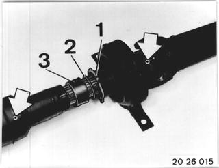
Loosen threaded sleeve (1). Mark propeller shaft position on slide with a punch, if propeller shaft was not already marked. Pull propeller shaft front sectiion out of slide. Installation: Lubricate slide with Longterm 2. Tighten threaded sleeve (1) after completing installation. Propeller shaft was balanced as an assembly and must not be displaced in slide. | 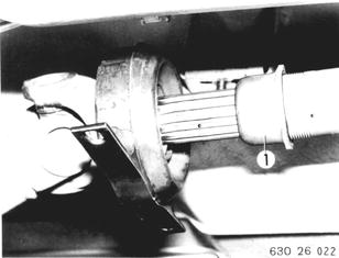 |
Remove circlip (2). Remove dust guard (3). | 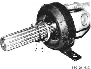 |
Pull off center bearing without dust guard with a standard puller (from Kukko). | 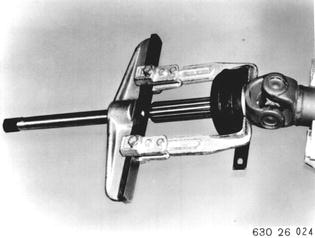 |
Installation: Knock center bearing on grooved ball bearing with Special Tool 24 1 050. Coat grooved ball bearing take-up surface with water. | 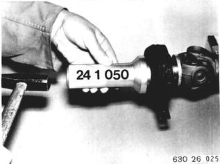 |
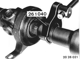
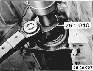
Vehicles after change point in 1982 REPLACING PROPELLER SHAFT CENTER MOUNT ASSEMBLY Version with Slide: Remove propeller shaft 26 11 000. Unscrew threaded sleeve with Special Tool 26 1 040. Pull off front propeller shaft section. Important! Propeller shaft was balanced in assembled state and must not be turned in slide. Punch mark an unmarked propeller shaft.  26 11 000 26 11 000
|  |
Insatallation: Lubricate slide with Molykote Longterm 2**. Slide on threaded sleeve (1), washer (2) and rubber ring (3). Assemble propeller shaft that punch marks are aligned.  * Source: HWB * Source: HWB
|  |
Note: Propeller shaft sections are mounted to have universal joints in one plane. If slide had been taken apart without punch marking, only wrong installation by 180° is possible because of balancing. | 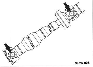 |
Installation: Tighten threaded sleeve with Special Tool 26 1 040 after finishing installation: Tightening torque*.  * See Specifications * See Specifications
|  |
Lift out circlip (4) and remove dust guard (5). | 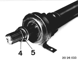 |
Pull off center mount complete with grooved ball bearing. | 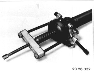 |
Press grooved ball bearing into center mount. | 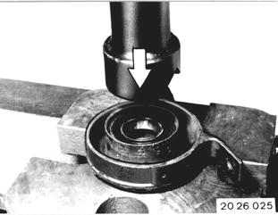 |
Slide on dust guard (1). Press on center mount with Special Tool 24 1 050. Installation: Check installed position of dust guard - flush with center mount. Important! Check clearance of center mount. | 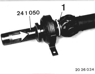 |
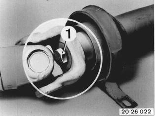
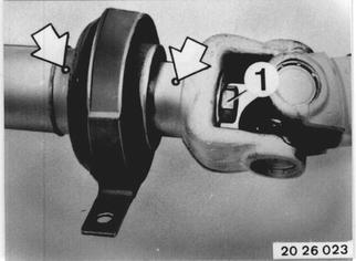
Propeller Shaft without Slide: Remove propeller shaft 26 11 000. Unscrew bolt (1). Punch mark propeller shaft sections to each other. Pull off front propeller shaft section. Important! Propeller shaft was balanced as an assembly - splines must not be displaced.  26 11 000 26 11 000
|  |
Installation: Assemble propeller shaft that punch marks are aligned. Lock bolt (1) with a bolt cement**. Tightening torque*.  * See Specifications * See Specifications ** Source: HWB ** Source: HWB
|  |
Pull off center mount complete with grooved ball bearing. | 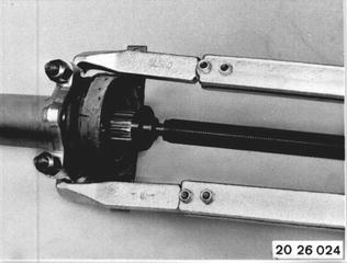 |
Press grooved ball bearing into center mount. |  |
Drive on center mount with Special Tool 24 1 040. Important! Check clearance between center mount and dust guard. | 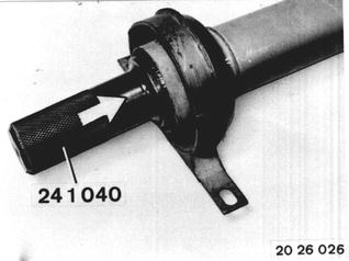 |