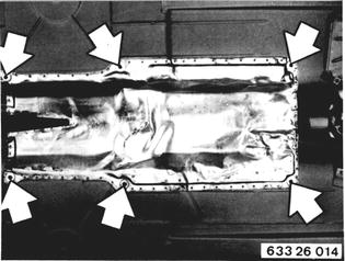
REMOVING AND INSTALLING PROPELLER SHAFT Remove exhaust assembly 18 00 020. 1980 Models: Detach heat shield.  18 00 020 18 00 020
|  |
 |
|
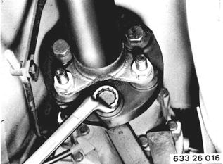
To prevent stress in Giubo coupling and therefore vibration and drumming, use Special Tool 26 1 011 for removal and installation of propeller shaft. Unscrew bolts. Installation: Use stop nuts only once. | 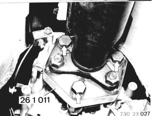 |
Tighten Special Tool 26 1 011 until bolts can be removed by hand. | 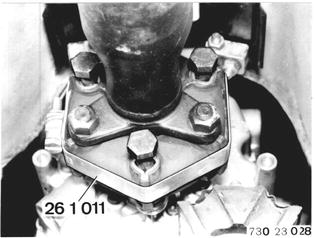 |
Installation: To prevent stress in Giubo coupling, only tighten nuts (never bolts). Tightening torque¹). Tighten nuts before removing special tool.  ¹) See Specifications ¹) See Specifications
|  |
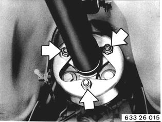
Detach propeller shaft at final drive. | 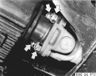 |
Installation: Use stop nuts only once. Tighten nuts to specified torque¹) with Special Tool 26 1 050 and a torque wrench.  ¹) See Specifications ¹) See Specifications
| 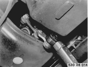 |
Remove heat shield. | 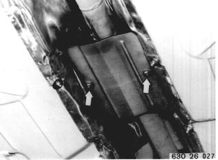 |
Detach center bearing. Installation: Preload center bearing forward in direction (A) by about 2 mm (0.080´´). | 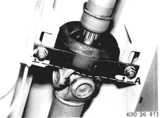 |
Bend down propeller shaft and pull out of centering pin on transmission. | 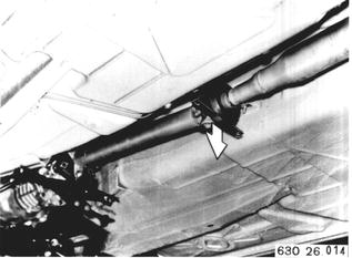 |
Installation: Check center, lubricating with Longterm 2 if necessary. Replace a damaged center. | 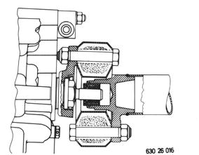 |
Installation: Propeller shaft was balanced in an assembled state and must therefore be replaced as an assembly. Tighten threaded sleeve (1) after installation. | 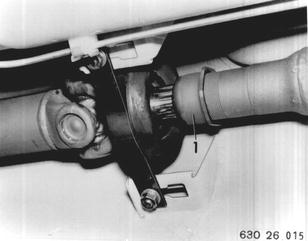 |
Installation: Align propeller shaft with Special Tool 26 1 000. a) Lateral adjustment of center bearing. b) Use of max. 3 mm (0.120´´) shims on center bearing. Misaligned propeller shafts will often be cause of vibrations or drumming. | 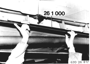 |
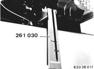
If there are vibrations or drumming, check and adjust propeller shaft´s deflection angle with Special Tool 26 1 030. Place special tool on oil pan flange and measure engine´s angle. | 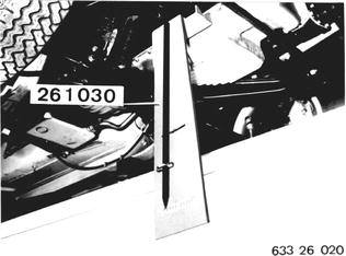 |
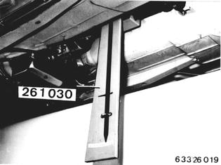
Place special tool on propeller shaft front section and measure angle. Check deflection angle¹) of Giubo coupling or hardy disc and, if necessary, correct by using up to 3 mm (0.120´´) shims on transmission suspension or center bearing. Example: Engine angle........................2° 30´ Propeller shaft angle............-2° 00´ ------------------------------------------------------ Deflection angle of Giubo...+0° 30´ coupling or hardy disc  ¹) See Specifications ¹) See Specifications
|  |
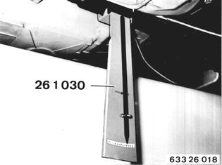
Place special tool on propeller shaft rear section and measure angle. Check deflection angle¹) of center bearing and, if necessary, correct by using up to 3 mm (0.120´´) shims on transmission suspension or center bearing.  ¹) See Specifications ¹) See Specifications
|  |
Apply special tool on final drive with help of a flat iron bar and measure angle. Check deflection angle¹) of universal joint and, if necessary, correct by using up to 3 mm (0.120´´) shims on center bearing.  ¹) See Specifications ¹) See Specifications
|  |
Rattling or Scraping Noise: Propeller shaft was balanced as an assembly and therefore may not be turned in the slide. Mark an unmarked propeller shaft with a punch. | 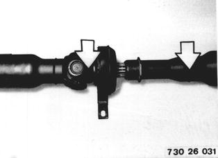 |
Remove threaded sleeve (1) and felt ring. Clean keyways with Tri and spray with Activator Q. Coat with green Loctite. Install propeller shaft and tighten threaded sleeve. Drying time is about 2 hours. | 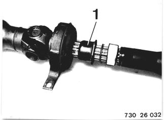 |
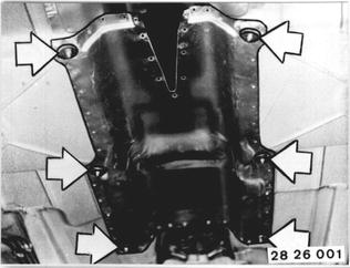
Vehicles after change point in 1982 REMOVING AND INSTALLING PROPELLER SHAFT Remove exhaust assembly - 18 00 020. Unscrew heat shield.  * See Specifications * See Specifications
|  |
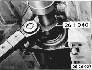
Version with Front Joint Disc or Universal Joint: Loosen threaded sleeve several turns with Special Tool 26 1 040. Installation: Tighten threaded sleeve with Special Tool 26 1 040 after finishing installation. Tightening torque*.  * See Specifications * See Specifications
|  |
Unscrew propeller shaft on transmission. | 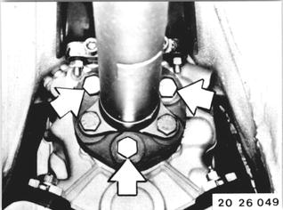 |
Version with Bolted Vibration Damper: The vibration damper is mounted on the transmission end output flange. | 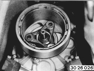 |
Unscrew propeller shaft on transmission. Turn vibration damper 60°C and place it on the rubber coupling. The vibration damper is removed together with the propeller shaft. | 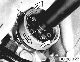 |
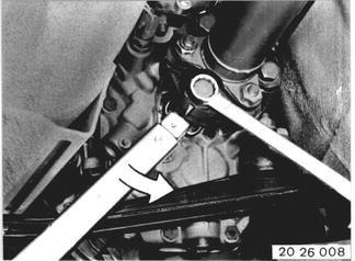
Installation: Replace stop nuts. Tightening torque*. Important! Only turn nuts or bolts on the flange end whenever permitted by design, in order to avoid tension in the joint disc.  * See Specifications * See Specifications
|  |
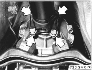
Front Universal Joint Version: Unscrew propeller shaft on transmission. Installation: Replace stop nuts. Align cross member if necessary and tighten nuts with a torque wrench. Tightening torque*.  * See Specifications * See Specifications
|  |
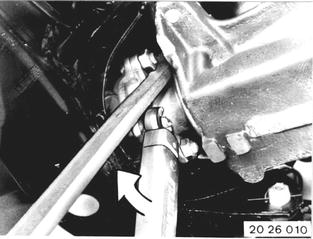
Unscrew propeller shaft on final dirve. | 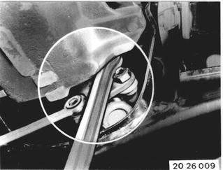 |
 |
|
Unscrew center mount. Installation: Preload center mount forward by distance A = 4 to 6 mm (0.157 to 0.236´´). | 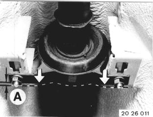 |
Bend propeller shaft down and pull out of centering pin on transmission. Installation: The propeller shaft had been balanced as an assembly and may only be replaced as such. Check center, lubricating with Molykote Longterm 2 if necessary. Replace a damaged center. | 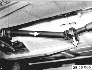 |
Installation: Check center, lubricating with Molykote Longterm 2 if necessary. Replace a damaged center. | 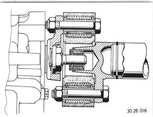 |
Installation: Tighten threaded sleeve with Special Tool 26 1 040 after finishing installation. Tightening torque*.  * See Specifications * See Specifications
|  |
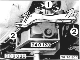
Version with Constant Velocity Joint: Support transmission with Special Tools 24 0 120 and 00 2 020. Take off nuts and washers (1). Loosen nuts (2). Push back the transmission carrier. Installation: Tightening torque*.  * See Specifications * See Specifications
|  |
Unscrew nuts. | 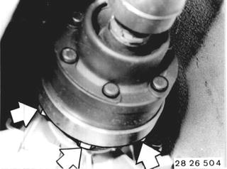 |
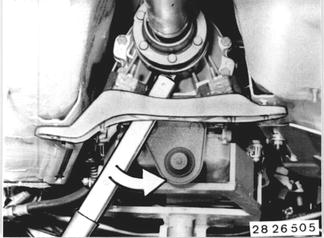 |
|
Unscrew propeller shaft on final drive. |  |
 |
|
Unscrew center mount. Installation: Preload center mount forward by distance A = 4 to 6 mm (0.157 to 0.236´´). | 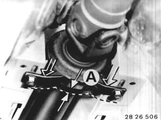 |
Bend propeller shaft down and pull out of transmission flange. | 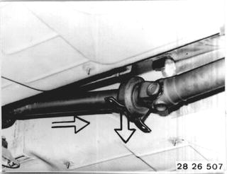 |
Important! Constant velocity joint is not encapsulated. Cover constant velocity joint or use the transportation cap. | 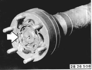 |
Installation: Use gasket between constant velocity joint and transmission flange. | 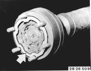 |
BMW 628csi - M635csi (M6)»26 - Propeller shaft»26 11 000 - Propeller shaft - removing and installing