Vehicles after change point in 1982 ELIMINATING PROPELLER SHAFT VIBRATION AND NOISE Vibration or Noise: Requirements: Propeller shaft in perfect optical condition. Balance propeller shaft, if balance plates are missing and propeller shaft is suspected to have imbalance (refer to instructions supplied with the balancing machine): Important! The wheel suspension of the driven wheels must be supported when trial running on a jacked up car (deflection angles of output shaft). The maximum speed of the car in jacked up state and on rollers must never be exceeded. Conform with safety regulations! | 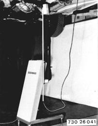 |
||||||
Aligning Propeller Shaft: Center propeller shaft, using Special Tool 26 1 020 if necessary. | 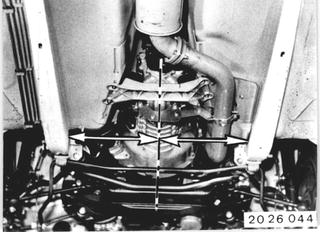 |
||||||
Checking Deflection Angles of Joints and Correcting If Necessary: Apply Special Tool 26 1 030 (gage) on the oil sump flange and measure angle of engine. Note: When correcting a deflection angle by installing shims, remember that the deflection angle of the adjacent joints will also change. | 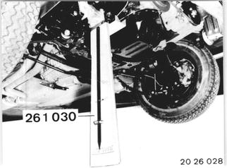 |
||||||
If Oil Pan Flange is Not Accessible: Apply Special Tool 26 1 030 with an auxillary rail (steel ruller) and measure angle of engine inclination. Note: When correcting a deflection angle by installing shims, remember that the deflection angle of the adjacent joints will also change. | 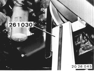 |
||||||
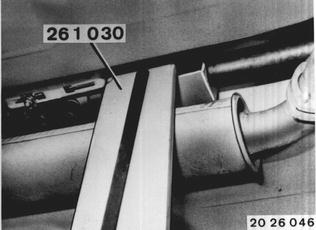
Apply gage on propeller shaft front section and measure angle. Measure deflection angle* of joint disc and, if necessary, correct it with shims (up to max. 3 mm or 0.118") on the transmission suspension or center mount. Example:
 * See Specifications * See Specifications
|  |
||||||
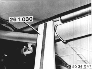
Apply gage on propeller shaft rear section and measure angle. Measure deflection angle* of center mount and, if necessary, correct it with shims (up to max. 3 mm or 0.118") on the transmission suspension or center mount.  * See Specifications * See Specifications
|  |
||||||
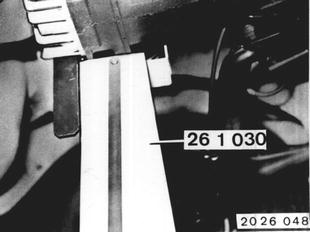
Apply gage on final drive with help of a rail (steel ruler) and measure angle. Determine deflection angle* of universal joint and, if necessary, correct on center mount by installing shims (up to max 3 mm or 0.118").  * See Specifications * See Specifications
|  |
||||||
Hard Movement on Side: Note: The propeller shaft was balanced in assembled state and must not be turned in the slide. Mark an unmarked propeller shaft with a punch. | 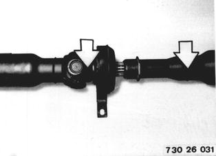 |
||||||
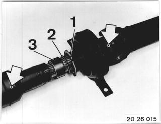
Remove threaded sleeve (1), wsher (2) and rubber ring (3). Check rubber ring, replacing if necessary. Disconnect propeller shaft on slide. Clean and lubricate keyway with Molykote Longterm 2**. Assemble propeller shaft that the punch marks are aligned.  ** Source: HWB ** Source: HWB
|  |
||||||
Note: Propeller shaft sections are mounted in such a manner that universal joints are in one plane. If the slide had been disassembled by mistake without punch marking, ir will only mean the possibility of installing the propeller shaft wrong by 180° because of balancing. | 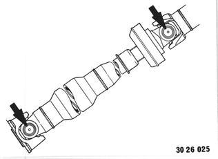 |
||||||
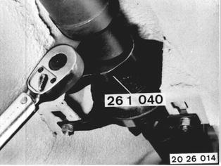
After Finishing Installation: Tighten threaded sleeve with Special Tool 26 1 040. Tightening torque*  * See Specifications * See Specifications
|  |
BMW 628csi - M635csi (M6)»26 - Propeller shaft»26 00 001 - Propeller shaft vibration and noise - eliminate