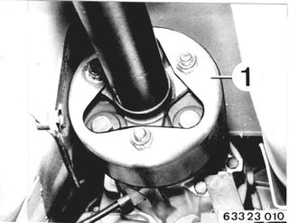
Vehicles before change point in 1982 REMOVING AND INSTALLING/SEALING TRANSMISSION COVER Remove exhaust assembly 18 00 020. Version with Heat Shield: Detach heat shield at body. Disconnect guard (1) at propeller shaft.  18 00 020 18 00 020
|  |
Detach coupling at transmission. | 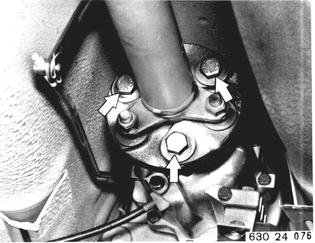 |
Installation: Tighten nuts to specified torque¹) with a standard 19 mm socket and torque wrench. Important: Only tighten nuts (never bolts) to prevent stress in coupling.  ¹) See Specifications ¹) See Specifications
| 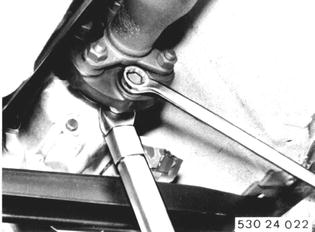 |
Detach heat shield. Detach center bearing. Installation: Preload center bearing forward by 2 mm (0.080´´). | 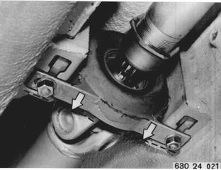 |
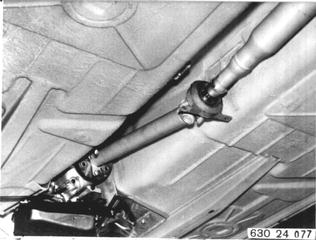
Slide propeller shaft together at slide, bend down and pull off of centering pin. Installation: Align propeller shaft with Special Tool 26 1 000 (see 26 11 000).  26 11 000 26 11 000
|  |
Remove lockplate. Installation: Lock lockplate in groove of output flange. | 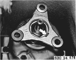 |
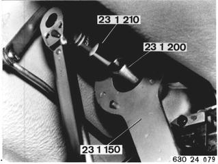
Install Special Tool 23 1 200. Hold output flange with Special Tool 23 1 150. Unscrew collar nut¹) with Special Tool 23 1 210. Pull off output flange. Installation: Install collar nut with Curil K 2 or Loctite No. 572.  ¹) See Specifications for tightening torque ¹) See Specifications for tightening torque
|  |
Support transmission with Special Tools 23 0 000 and 00 2 020. Remove cross member. Lower transmission. Detach transmission extension. | 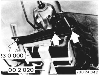 |
Unscrew nut (2) and loosen stud (3) by about 3 turns. Pull off governor. | 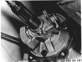 |
Installation: Press piston rings together slightly and slide governor on governor flange at the same time. Unscrew stud to facilitate finding depression in output shaft. Secure governor with stud in depression of output shaft and lock by counterpunching. | 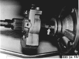 |
Detach bearing flange. Important: Thrust washer (4) and needle bearing (5). Replace gasket (6). | 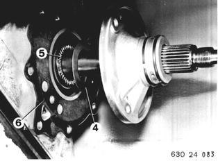 |
Vehicles after change point in 1982 RREMOVING AND INSTALLING/ SEALING TRANSMISSION EXTENSION Remove exhaust assembly 18 00 020. Unscrew joint disc on transmission.  18 00 020 18 00 020
| 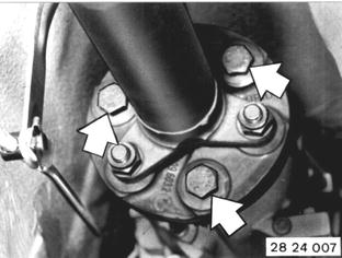 |
Installation: Replace stop nuts. Tighten nuts to specified torque* with a standard 19 mm socket and torque wrench. Important! Only tighten nuts (never bolts) to avoid stress in joint disc. |  |
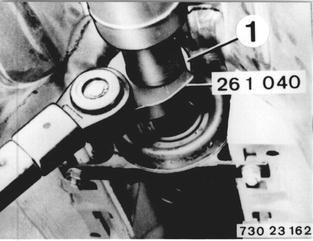
Loosen screw-on ring (1) several turns. Installation:L Tighten screw-on ring (1) with Special Tool 26 1 040 after finishing installation. Tightening torque*.  * See Specifications * See Specifications
|  |
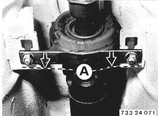
Unscrew center mount. Installation: Preload center mount forward by distance A = 2 to 4 mm (0.079 to 0.157´´). Tightening torque*. Bend propeller shaft down and pull off of centering pin. Important! Suspend propeller shaft from car on piece of wire.  * See Specifications * See Specifications
|  |
Remove lockplate. Installation: Lock lockplate in output flange groove. |  |
Apply Special Tool 23 1 200. Hold output flange with Special Tool 23 1 150. Unscrew collar nut with Special Tool 23 1 210. Pull off output flange. Installation: Install collar nut with Curil K2 or Loctite No. 572** and tighten to correct torque*.  * See Specifications * See Specifications ** Source: HWB ** Source: HWB
|  |
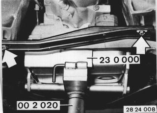
Support transmission with Special Tools 23 0 000 and 00 2 020. Remove cross member. Lower transmission. Unscrew transmission extension. Tightening torque*.  * See Specifications * See Specifications
|  |
Loosen nut (2) and unscrew stud (3) about 3 turns. Pull off governor. |  |
Installation: Compress piston rings slightly and push governor on to governor flange. Important! Punch mark (1) on output shaft must be aligned with opening (2) in governor flange. Mount governor - tightening torque*.  * See Specifications * See Specifications
|  |
Unscrew bearing flange. Important! Thrust washer (4) and needle bearing (5). Replace gasket (6). Tightening torque*.  * See Specifications * See Specifications
|  |
BMW 628csi - M635csi (M6)»24 - Transmission-automatic»24 11 050 - Transmission cover - removing and installing/sealing