| |
Vehicles after change point in 1982
REMOVING AND INSTALLING THROTTLE VALVE NECKS
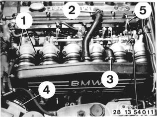
Unscrew bolts (1) on all six throttle valve
necks (2 ... 4).
Loosen hose clamps (2 ... 4).
Disconnect accelerator cable (5).
Take off the intake manifold, pulling off the
connecting hose between the manifold and
crankcase.
|  |
| |
Installation:
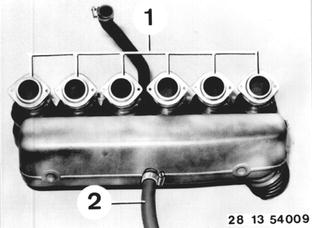
Check O-rings (1), replacing if necessary.
Check sleeves, replacing if necessary.
Replace connecting hose (2) between intake
manifold and crankcase.
|  |
| |
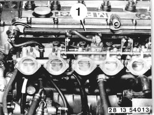
Pull off plugs on cold start valve, throttle
bypass valve and throttle valve switch.
Pull off plug plate (1) on fuel injectors.
|  |
| |
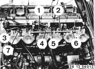
Pull off vacuum hose (1) for fuel pressure
regulator and (2) for heater temperature
sensor.
Disconnect fuel return pipe (3).
Unscrew nuts (4 and 5).
Unscrew bolts (6 and 7).
Take off injection tube with fuel injectors.
|  |
| |
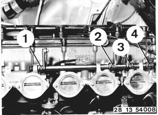
Drive out pins (1 ... 4).
Note:
The shaft runs on a needle bearing.
Do not pull a dirty shaft through the bearing.
Do not damage the shaft with tools (pliers) -
danger of damaging the needle bearing.
Installation:
Replace pins.
Lubricate bearing surfaces and joints of the
throttle valve linkage with Molykote Longterm
after cleaning.
|  |
| |
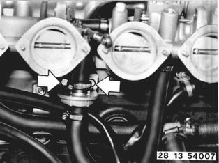
Unscrew nuts and take off the throttle bypass
valve.
Disconnect air hoses.
|  |
| |
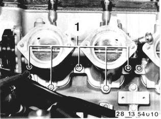
Unscrew nuts (1) on all throttle valve necks.
Take off complete throttle valve necks.
|  |
| |
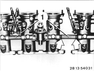
Take off connecting pipes.
Separate throttle valve necks.
Check O-rings of connecting pipes, replacing
if necessary.
|  |
| |
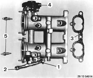
(Throttle Valve Necks for Cylinders 1 and 2)
Unscrew nut (1).
Take off push rod (2).
Replace gasket (3).
Unscrew throttle valve switch.
Unscrew throttle screws.
Check O-rings (5), replacing if necessary.
Installation:
Screw in throttle screws carefully to fit tight and then loosen by 1 and 1/2 turns.
|  |
| |
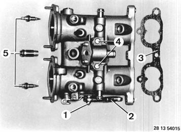
(Throttle Valve Necks for Cylinders 3 and 4)
Unscrew nut (1).
Take off push rod (2).
Replace gasket (3).
Unscrew bolts (4) and take off bypass housing (replace gasket).
Unscrew throttle screws.
Check O-rings, replacing if necessary.
Installation:
Screw in throttle screws carefully to fit tight and then loosen by 1 and 1/2 turns.
Screw in central air bypass screw to fit tight and then loosen by 8 turns.
|  |
| |
(Throttle Valve Necks for Cylinders 5 and 6)
Loosen nut (1) and take off push rod (2).
Replace gasket (3).
Lift out retainer (4).
Unscrew throttle screws.
Check O-rings (5), replacing if necessary.
Take off lever bearing (7), sleeves (6), spring (8) and washer (9).
Installation:
Screw in throttle screws carefully to fit tight and then loosen by 1 and 1/2 turns.
Preload spring (8) with approximately 1/2 turn.
|  |
| |
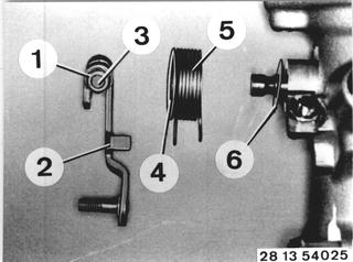
Note:
A Basic adjustment of the throttle valve necks
is only necessary after replacing parts or in
case of a loose clamping screw.
Unscrew nut (1).
Take off throttle lever (2) with screw (3).
Remove sleeve (4) with spring (5).
Check washer (6).
Installation:
Preload spring (5) by about 1/2 of a turn.
Adjusting Requirement:
Component temperature approx. 20°C
(68°F).
|  |
| |
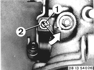
Loosen nut (2).
Turn idle stop screw (1) in direction of arrow
by about 1/10th of a turn.
Tighten nut (2) again.
|  |
| |
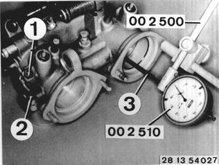
Close the throttle valves.
Press the throttle lever against idle stop screw
(1) and tighten nut (2).
Mount dial gage 00 2 510 with extension (3)
and holder 00 2 500 on the throttle valve neck.
Dial gage tip bearing with preload on deepest
possible position of the throttle valve.
|  |
| |
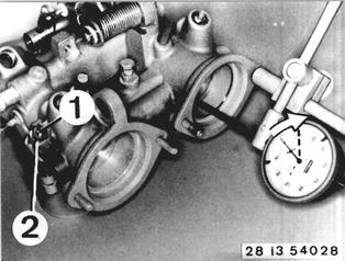
Loosen nut (2).
Adjust the throttle valve with idle stop screw
(1) to be about 0.1 + 0.05 mm (0.039 + 0.002´´)
below the edge (about 1/10th of a turn).
Tighten nut on idle stop screw (1) and lock with
paint.
|  |
| |
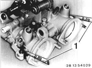
Checking Axial Clearance:
A 0.2 mm (0.008´´) thick feeler gage blade (3)
must fit easily between the circlip or throttle
lever and housing on the left and right sides
simultaneously with a closed throttle valve and
a room temperature of about 20°C (68°F).
Check whether throttle valves move easily at
operating temperature.
|  |
| |
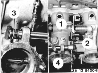
Adjusting Throttle Valve Linkage:
Levers (1 and 2) must be aligned.
Correct with washers (3).
Check outside diameter of washers - washers
should bear on the needle bearing and not on
the console.
(4) = 5 mm (0.197´´) dia. pin or drill bit
|  |
| |
Axial Clearance:
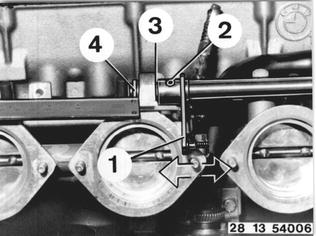
Hold lever (1) on shaft with a 5 mm (0.197´´)
dia. pin (2).
Measure axial clearance with a calipers and
adjust to 0.1 ... 0.2 mm (0.004 ... 0.008´´)
with washers (3).
Do not change the number of washers (4).
|  |
| |
Loosen throttle valve switch.
Adjust throttle valve switch only after
adjusting the throttle valve linkage.
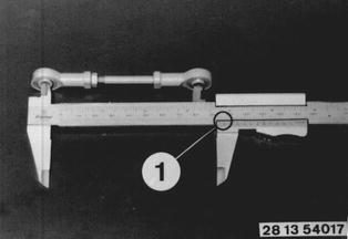
Adjust push rods.
Adjust push rod (cylinders 5 and 6) to 1 =
97.5 ± 0.4 mm (3.839 ± 0.016´´).
|  |
| |
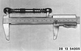
Adjust push rods of cylinders 1 ... 4 to a
distance of approx. 100 mm (3.937´´) and
install.
|  |
| |
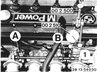
Mount Special Tools 00 2 510 and 00 2 500
(dial gage with holder) on the staybolts.
Apply dial gage on lever (1) with preload.
Shorten push rods (A and B) one after the
other until the dial gage needle starts to move.
All three throttle levers are bearing on the idle
stop in this position.
|  |
| |
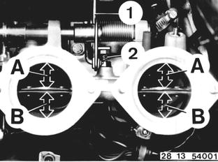
Adjusting Full Load Stop:
Move cable lever (1) into full load position.
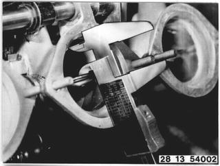
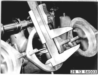
Measure distance (A or B) with a calipers and
note the value.
Calculate the mean value of the 6 throttle
valve necks and determine the deviation from
the design distance.
Adjust all six throttle valves in direction of
design distance simultaneously with screw (2).
|  |
| |
Distance A = 21,7 mm (0,854") (design distance).
|  |
| |
Distance B = 22,7 mm (0,894") (design distance).
|  |