Checking Engine Vent System for Leaks Check gasket in oil filler cap. | 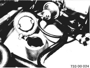 |
Check hose for crankcase breathing for tight fit or damage. | 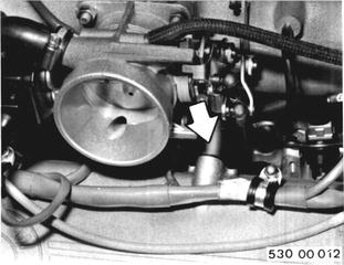 |
SERVICE JOBS ON ENGINE ELECTRICAL SYSTEM Important: Carry out all jobs on transistor ignition system only with engine stoppede and ignition truned off. DANGER! Checking Tightness of Wire Connections Check wires and plugs on engine for correct routing and tight fit. If necessary, bend wire plugs carefully with a pliers. | 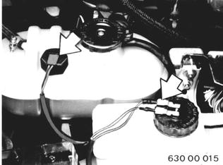 |
Adjusting Ignition Timing (BMW 633 form 1980 Models) Breakerless Version: Important: Stop engine and turn off ignition prior to performing any work on a breakerless transistor coil ignition system. DANGER! Requirements for exact ignition timing adjustments: Engine at operating temperature. Dwell angle correct. Connect BMW service test unit or digital tester according to the operating instructions. | 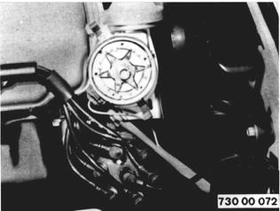 |
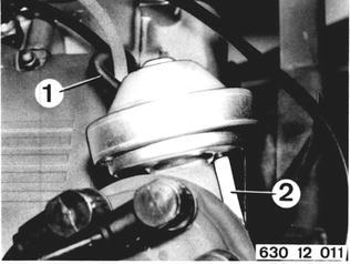
The dwell angle is given by design and can´t be changed. Checking Dwell Angle¹): Pull off vacuum hoses for advance (1) and retard (2).  ¹) See microfilmed specifications ¹) See microfilmed specifications
|  |
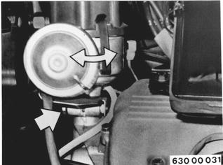
Start engine. Pre-program BMW tester speed control¹). Also refer to operating instructions for BMW service test unit or digital tester. Accelerate engine to at least the pre-programmed speed¹). Read dwell angle¹) from tester. Correction: Stop engine and turn off ignition. Loosen distributor mounting bolt and correct ignition timing by turning the distributor. Recheck system.  ¹) See microfilmed specifications ¹) See microfilmed specifications
|  |
Replacing Distributor Cap and Finger Take off distributor cap. Pull out ignition wires and connect to new distributor cap. Installation: Watch order of ignition wires (1-5-3-6-2-4). | 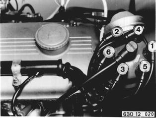 |
Pull off distributor rotor and install new rotor. Important: Distributor rotor must engage in slot in distributor shaft. Note tab on dust cap. | 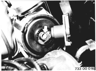 |
Checking Vacuum Control Hoses for Tight Fit and Correct Routing | 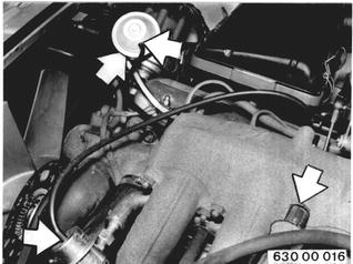 |
Checking Fuel Evaporation System Check tightness of hose lines and connections on fuel evaporation system. Check filter plate on carbon filter for plugging, replacing carbon filter if necessary. | 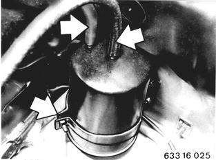 |
Checking Fuel System for Leaks Check tank cap and gasket, fuel tank and lines for leaks or damage (visual inspection). | 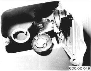 |
SERVICE JOBS ON COOLING SYSTEM Tightening Hose Clamps on Cooling System Check coolant hoses for damage and correct routing. | 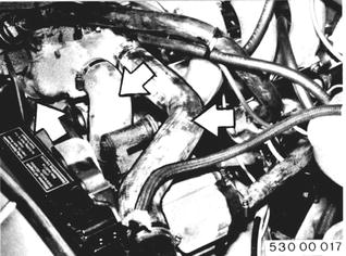 |
Tighten all hose clamps on radiator and engine. | 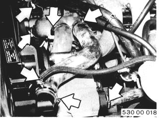 |
Checking Power Stearing Pump and Function of Power Steering A) Pump Always check delivery pressure of pump first. Detach pressure line (1) at pump. In its place, connect pressure line (2) from pressure tester 32 4 000. Important: Never reuse drained oil. | 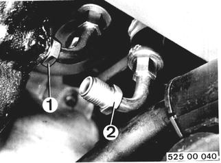 |
Connect pressure line (1), detached from pump, on pressure tester. | 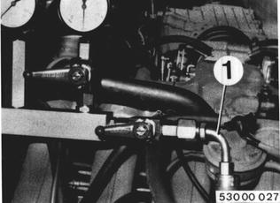 |
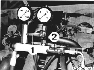
Shut valve (1). Open valve (2) and bleed hydraulic system with engine running at idle Speed 32 13 006. Engine must have operating temperature. After bleeding, shut valve (2) for max. 10 seconds and take pressure reading. Pressure could be less than pressure of 110 bar (1600 psi) as on pump´s data plate by max. 10 %. Pressure Inadequate: a) Check belt tightness. b) Replace pump. Important: Valve (1) must be shut for high pressure tests, because otherwise pressure gage (max. 16 bar/ 230 psi) would be destroyed.  32 13 006 32 13 006
|  |
B) Power Steering Lift car. Limit steering lock by 1/2 to 3/4 steering wheel turn before reaching final stop (wood or similar item). | 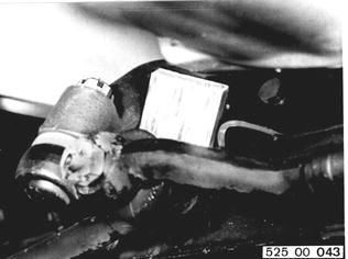 |
Let engine run. Pull steering wheel against final stop with a force of 100 N (22 lbs.) for approx. 5 seconds. Read pressure from pressure gage 32 4 000. Make same measurement at right lock. If determined pressure values are less than max. pump pressure¹), replace steering gear.  ¹) See Specifications of Group 32 ¹) See Specifications of Group 32
| 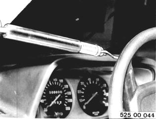 |
C) Checking Mechanical Steering Play (pressure point adjusted) Hold steering drop arm in straight ahead position with Special Tool 32 4 040. | 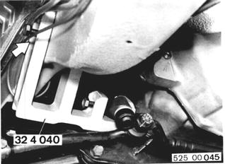 |
Open valve (2). Shut valve (1). Run engine having operating temperature at idle speed. Open valve (1). Read flow-through pressure. | 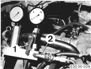 |
Paste strips of paper on steering wheel hub and casing upper section. Turn steering wheel anticlockwise carefully until pressure gage shows 1 bar (14 psi) more than the flow-through pressure. Mark position of steering wheel hub at (A). Turn steering wheel clockwise carefully until pressure gage 32 4 000 shows 1 bar (14 psi) more than flow-through pressure. Again mark position of steering wheel hub on (A). | 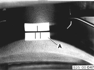 |
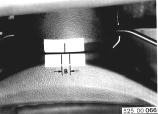
Total travel (B) must not exceed 7 mm (0.275´´). Check joint coupling, if 7 mm (0.275´´) are exceeded. Replace steering gear, if joint coupling is not cause. Remove pressure gage 32 4 000. Fill and bleed hydraulic system 32 13 006.  32 13 006 32 13 006
|  |
Tightening Bolts and Nuts of Steering Power steering pump to engine......Nm 22-24, Ft. Lbs. 16-17 Steering gear to front axle carrier......Nm 43-48, Ft. Lbs. 31-35 Joint coupling to joint flange......Nm 20-23, Ft. Lbs. 15-17 Joint flange to steering gear and steering spindle......Nm 25-28, Ft. Lbs. 18-20 Tie rod bolts......Nm 12-15, Ft. Lbs. 9-11 Tie rod castle nuts......Nm 35-40, Ft. Lbs. 25-29 Tie rod arm to steering knuckle......Nm 45-60, Ft. Lbs. 33-43 | |
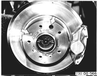
Parking Brake Liners: Remove and install rear wheel 36 10 300. Take off brake caliper, brake line remaining connected. Unscrew socket head bolt with a 4 mm wrench. Remove brake disc from axle shaft. Installation: Watch position of brake disc/axle shaft flange holes. Large hole of brake disc must align with large hole in axle shaft flange.  36 10 300 36 10 300
|  |
Check minimum thickness and condition of brake liners. Brake liners must not be less than 1.5 mm (0.060´´) at their thinnest point. Replace brake shoes, when liners reach 1.5 mm (0.060´´). | 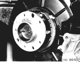 |
BMW 628csi - M635csi (M6)»00 - Maintenance and general information»00 00 090 A - Extra jobs for BMW inspection (60,000 mile intervals)