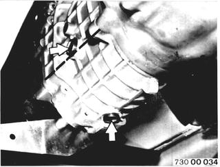
Changing Manual Transmission Oil Transmission at operating temperature. Unscrew filler plug and oil drain plug. Clean drain plug, check and install again. Add transmission oil. Refer to Service Information of Group 23 for approved oils. Installation: Tightening torque¹).  ¹) See Specifications of Groups 23 and 24 ¹) See Specifications of Groups 23 and 24 ¹) See Specifications of Group 23 and 24 ¹) See Specifications of Group 23 and 24
|  |
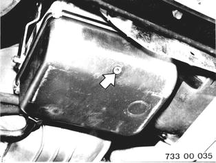
Changing Automatic Transmission Fluid Transmission at operating temperature. Pull out oil dipstick. Unscrew oil drain plug. Installation: Check seal, replacing if necessary. Tightening torque and volumes¹). Refer to Service Information of Group 24 for approved ATF. Check oil level.  ¹) See Specifications of Groups 23 and 24 ¹) See Specifications of Groups 23 and 24 ¹) See Specifications of Groups 23 and 24 ¹) See Specifications of Groups 23 and 24
|  |
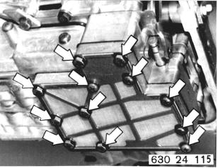
Replacing Oil Filter Screen at Control Unit Detach oil filler neck at oil pan. Remove oil pan. Remove oil filter screen and replace. Tightening torque¹). Important: New oil filter screen (larger mesh size).  ¹) See Specifications of Group 24 ¹) See Specifications of Group 24
|  |
Installed Order: (1) Gasket (2) Intermediate plate (3) Oil filter screen | 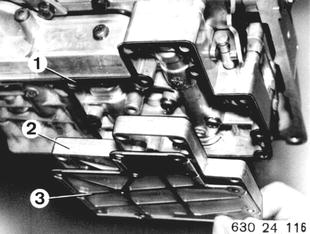 |
Installation: Secure oil pan with retaining brackets, that short arm presses down on oil pan. Important: Place magnetic disc (1) next to oil filter screen in oil pan. Install gasket (2). New version will have a second magnet. | 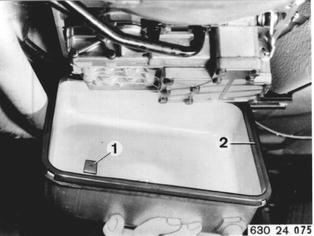 |
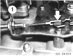
Version with Torx Bolts: Tighten torx bolts ti specified torque¹) with Special Tools 00 2 100 and 00 2 050.  ¹) See Specifications of Group 24 ¹) See Specifications of Group 24
|  |
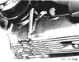
Changing Final Drive Oil Final drive at operating temperature. Unscrew oil filler and drain plugs. Clean drain plug, check seal and reinstall. Installation: Oil volume and tightening torque¹). Add oil to raise level to lower edge of filler opening. Refer to Service Information of Group 33 for approved oils.  ¹) See Specifications of Group 33 ¹) See Specifications of Group 33
|  |
Replacing Distributor Cap and Finger Take off distribtor cap. Pull out ignition wires and connect to new distributor cap. Installation: Watch order of ignition wires (1-5-3-6-2-4). | 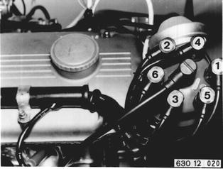 |
Pull off distributor rotor and install new rotor. Inportant: Distributor rotor must engage in slot in distributor shaft. Note tab on dust cap. | 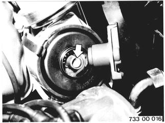 |
Checking Vacuum Control Hoses for Tight Fit and Correct Routing | 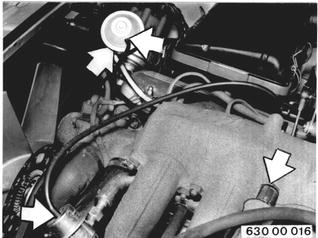 |
Checking Thermo Reactor The reactor works on the principle of self-ignition. Consequently it is important to check it for cracks and burns every 25,000 miles. The exact time of inspection is shown on the instrument panel by an indicator lamp actuated by an interval switch. Remove air cleaner with air flow sensor. | 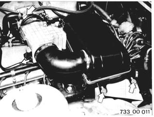 |
Unscrew heat shields. | 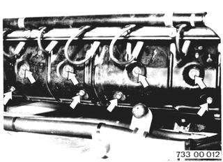 |
Check both reactors for cracks and burns, replacing if necessary. | 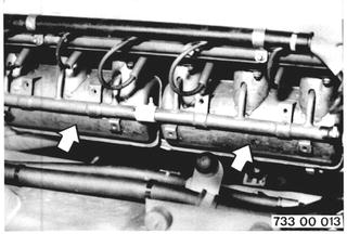 |
Press in contact button (1) on internal switch after completion of inspection or replacement of reactors. | 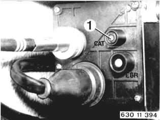 |
Replacing EGR Filter EGR filter must be replaced every 25,000 miles. Detach lines. Loosen bolts (1) until EGR filter can be removed toward rear. | 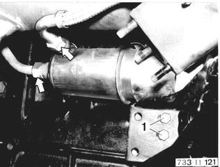 |
Press in contact button (2) on interval switch after replacement. | 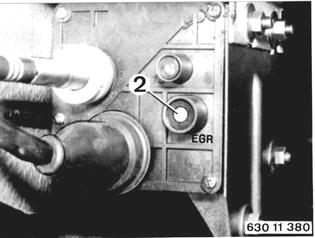 |
SERVICE JOBS ON CLUTCH Checking Clutch for Wear in Car If Special Tool 21 2 060 can be inserted into opening of slave cylinder against the stop, liners are good. | 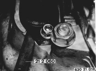 |
Drive plate is worn and must be replaced, if there is a gap of 5 mm (0.197´´) between Special Tool 21 2 060 and slave cylinder. | 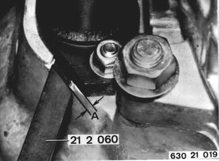 |
Checking Function fo Brake Booster Stop engine and depress brake pedal 10 times. Hold down brake pedal with force and start engine. System is okay, if brake pedal gives. If brake pedal does not give, there could be a defect in the check valve, vacuum hose, rubber ring between tandem brake master cylinder and brake booster. Engine vacuum supply could be insufficient or filter element in brake booster might be completely plugged. | 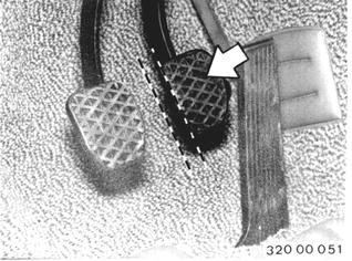 |
Checking and Aiming Headlight Beams Requirements: Correct tire pressures. Car on level surface. Center of rear seat loaded by a weight or person weighing 70 kg (155 lbs.). Check beams of low and high beam headlights with an optical aimer. Take off covers and correct beams with adjusting screws. (1) Vertical control (2) Lateral control | 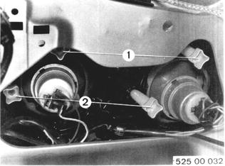 |
BMW 628csi - M635csi (M6)»00 - Maintenance and general information»00 00 079 - Extra jobs for BMW inspection (25,000 mile intervals)