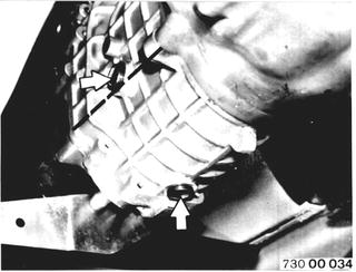
Changing Manual Transmission Oil Transmission at operating temperature. Unscrew filler plug and oil drain plug. Clean drain plug, check and install again. Add transmission oil. Refer to Service Information of Group 23 for approved oils Installation: Tightening torque¹).  ¹) See Specifications of Groups 23 and 24 ¹) See Specifications of Groups 23 and 24 ¹) See Specifications of Groups 23 and 24 ¹) See Specifications of Groups 23 and 24
|  |
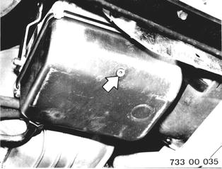
Changing Automatic Transmission Fluid Transmission at operating temperature. Pull out oil dipstick. Unscrew oil drain plug. Installation: Check seal, replacing if necessary. Tightening torque and volumes¹). Refer to Service Information of Group 24 for approved ATF. Check oil level.  ¹) See Specifications of Groups 23 and 24 ¹) See Specifications of Groups 23 and 24 ¹) See Specifications of Groups 23 and 24 ¹) See Specifications of Groups 23 and 24
|  |
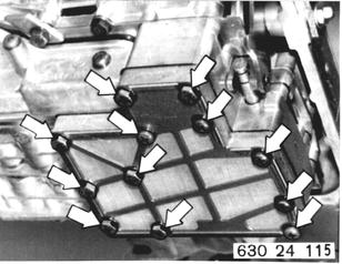
Replacing Oil Filter Screen at Control Unit Detach oil filler neck at oil pan. Remove oil pan. Remove oil filter screen and replace. Tightening torque¹). Inportant: New oil filter screen (larger mesh size).  ¹) See Specifications of Group 24 ¹) See Specifications of Group 24
|  |
Installed Order: (1) Gasket (2) Intermediate plate (3) Oil filter screen | 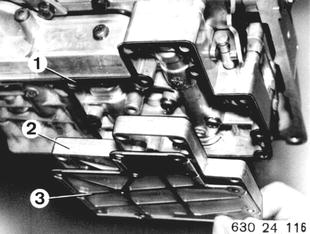 |
Installation: Secure oil pan with retaining brackets, that short arm presses down on oil pan. Important: Place magnetic disc (1) next to oil filter screen in oil pan. Install gasket (2). New version will have a second magnet. | 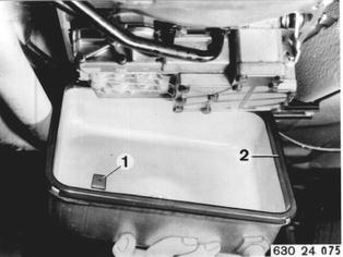 |
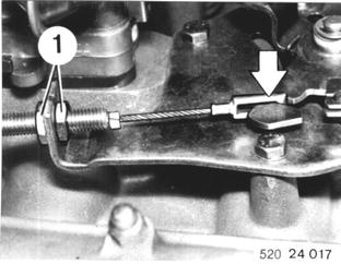
Version with Torx Bolts: Tighten torx bolts to specified torque¹) with Special Tools 00 2 100 and 00 2 050.  ¹) See Specifications of Group 24 ¹) See Specifications of Group 24
|  |
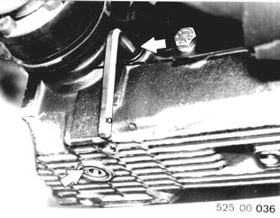
Changing Final Drive Oil Final drive at operating temperature. Unscrew oil filler and drain plugs. Clean drain plug, check seal and reinstall. Installation: Oil volume and tightening torque¹). Add oil to raise level to lower edge of filler opening. Refer to Service Information of Group 33 for approved oils.  ¹) See Specifications of Group 33 ¹) See Specifications of Group 33
|  |
Checking/Correcting Drive Belt Tightness A correctly tightened belt must give by distance (a) = 5 to 10 mm (0.197 to 0.394´´). Tightening Alternator Belt: Loosen alternator at tightening bar and upper mount. Swing out alternator and tighten bolts. |  |
Tightening Power Steering Belt: Loosen pump at holder and press down. Tighten mounting bolts. Open Flank Drive Belts: This type of drive belt should only give by 2 to 3 mm (0.080 to 0.120´´). | 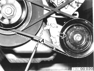 |
Checking/Correcting Tightness of Drive Belt for Air Conditioner Compressor | 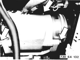 |
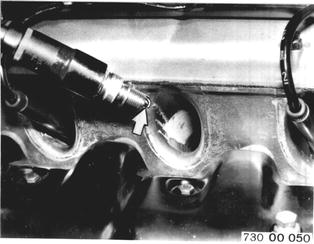
Checking or Replacing Spark Plugs Unscrew spark plugs. Clean or replace spark plugs covered with soot or oil. Electrode gap = 0.6 + 0.1 mm (0.024 + 0.004´´). Approved spark plugs¹). Tightening torque¹). Check spark plug wires and connectors for damage and tight fit.  ¹) See Specifications of Group 12 ¹) See Specifications of Group 12
|  |
Checking or Replacing Air Filter Cartridge Open fasteners. Remove air filter cartridge. Installation: Watch installed position of thw word "TOP". | 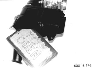 |
SERVICE JOBS ON FUEL TANK AND LINES Cleaning Initial Fuel Filter in Suction Pipe Remove cover from trunk floor. Detach hoses (2 and 3). (2) to fuel pump (3) return line Pull off plug (4). br/ge = brown/yellow br = brown br/sw = brown/black | 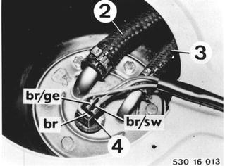 |
Loosen screws. Old Version: Turn fuel transmitter/suction tube anticlockwise with two crossed screwdrivers. | 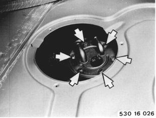 |
Clean fuel filter screen. Installation: Check gasket and round cord seal (19), replacing if necessary. Only when Replacing Fuel Transmitter: Remove transport guard (20). | 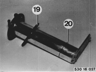 |
Replacing Main Fuel Filter Detach fuel hoses. Detach mounting bracket. Installation: Note direction of flow. | 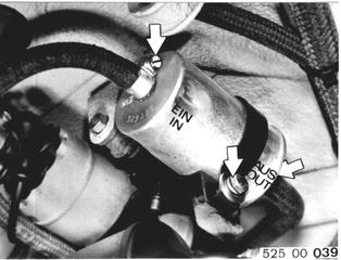 |
Replacing Oxygen Sensor Oxygen sensors must be replaced at 30,000 mile intervals. Disconnect plug connector (1). | 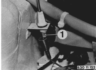 |
Unscrew and replace oxygen sensor (2). Installation: Apply light coat of copper paste, HWB No. 8122 9400 794 on threads. Tightening torque: 55 ± 5 Nm (40 ± 4 ft. lbs.). | 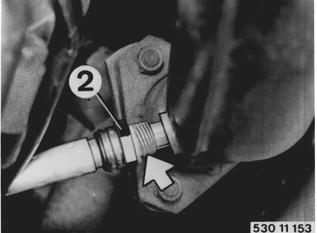 |
Press contact button (3) on service switch after replacing oxygen sensor. "OXYGEN SENSOR" lamp must go out. | 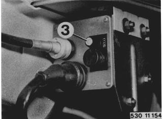 |
SERVICE JOBS ON CLUTCH Checking Clutch for Wear in Car If Special Tool 21 2 060 can be inserted into opening of slave cylinder against the stop, liners are good. | 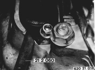 |
Drive plate is worn and must be replaced, if there is a gap of 5 mm (0.197´´) between Special Tool 21 2 060 and slave cylinder. | 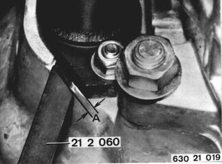 |
SERVICE JOBS ON FRONT AXLE Checking/Adjusting Front Wheel Bearing Play Remove and install grease cap with Special Tool 31 2 000. Remove cotter pin and unscrew castle nut. If necessary, replace grease packing. | 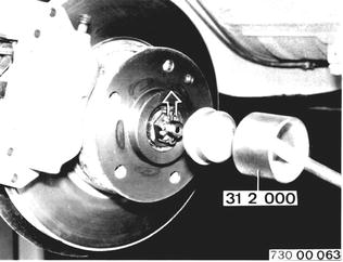 |
Tighten castle nut to 30 - 33 Nm (22 - 24 ft. lbs.) while turning wheel hub continuously. This will settle tapered pins and bearing inner races. Grease causing play will also be forced out. Turn tightened bearing assembly at least 2 more turns. In so doing, do not loosen or tighten castle nut any further. | 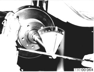 |
Loosen castle nut until there is axial bearing play, the hub being turned again. Tighten castle nut by max. 3 Nm (2 ft. lbs.), then turn back to nearest hole and lock with cotter pin. Checking Axial Bearing Play: Tabbed disc (1) must move without noticeable resistance. | 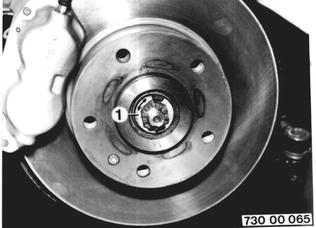 |
Tightening Bolts and Nuts Support bearing to wheel house......Nm 22-24, Ft.Lbs. 16-17 Front axle carrier to engine carrier......Nm 43-48, Ft.Lbs. 31-35 Control arm to front axle carrier......Nm 81-90, FT.Lbs. 59-65 Stabilizer to control arm......Nm 70-90, Ft.Lbs. 51-65 Bracket for stabilizer......Nm 47-52, Ft.Lbs. 34-38 | |
Checking Function of Brake Booster Stop engine and depress brake pedal 10 times. Hold down brake pedal with force and start engine. System ist okay, if brake pedal gives. If brake pedal does not give, there could be a defect in the check valve, vacuum hose, rubber ring between tandem brake master cylinder and brake booster. Engine vacuum supply could be insufficient or filter element in brake booster might be completely plugged. | 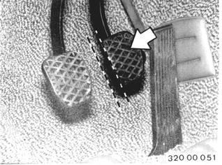 |
Checking and Aiming Headlight Beams Requirements: Correct tire pressures. Car on level surface. Center of rear seat loaded by a weight or person weighing 70 kg (155 lbs.). Check beams of low and high beam headlights with an optical aimer. Take off covers and correct beams with adjusting screws. (1) Vertical control (2) Lateral control | 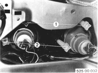 |
BMW 628csi - M635csi (M6)»00 - Maintenance and general information»00 00 079 A - Extra jobs for BMW inspection (30,000 mile intervals)