Vehicles before change point in 1982 REMOVING AND INSTALLING BRAKE BOOSTER WITH TANDEM BRAKE MASTER CYLINDER Function Test: Stop engine and operate brake pedal 10 times. Hold brake pedal down and start engine. System is good, if brake pedal gives slightly. If brake pedal does not give, there could be a defect in check valve, vacuum hose, rubber ring between tandem master cylinder and brake booster, or insufficient engine vacuum, or filter element of brake booster could be fully plugged. | |
Checking Engine Vacuum for Brake Booster: Detach vacuum hose from check valve. Install Special Tool 34 2 100 between brake booster and check valve. Check available vacuum when releasing accelerator from an engine speed of 3000 rpm (engine having operating temperature). Min. value: - 0.65 bar (6psi) vacuum. Repeat test several times. Min. value with engine running at idle speed as specified and having operating temperature: - 0.40 bar (bpsi) vacuum. | 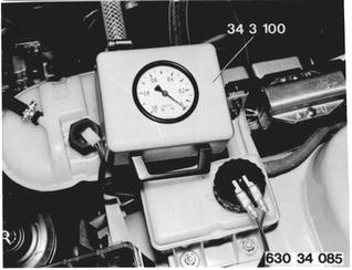 |
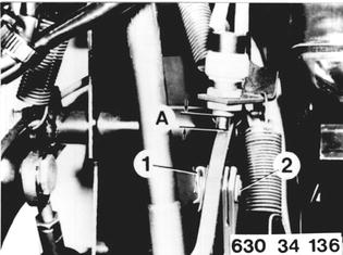
Detach and attach instrument panel trim at bottom left - 51 45 180. Remove clip (1) and pin (2) from piston rod. Installation: 5 to 6 mm (0.197 to 0.236´´) of contact pin from stop light switch must be seen when against stop on brake pedal.  51 45 180 51 45 180
|  |
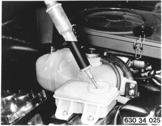
Draw off brake fluid from tank with a syringe reserved solely for this purpose. Installation: Bleed brakes - 34 00 046.  34 00 046 34 00 046
|  |
 |
|
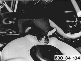
Unscrew nuts and lay back holder with attached parts. Hoses and attached parts remain connected. | 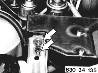 |
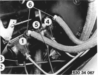
Remove and install air cleaner. Detach hoses at tandem master cylinder and tie them up. Important: Don´t spill fluid out of pipe elbow - remove carefully by pulling up. If rough treatment is applied, pipe could break in bend. Make sure that sealing plugs (6) fit properly in tandem master cylinder. Detach brake lines. 1 Front, right ............) 2 Front, left...............) 1st brake circuit 3 Rear wheel brakes) 4 Front, right.............) 5 Front, left...............) 2nd brake circuit Installation: Torque values¹).  ¹) See Specifications ¹) See Specifications
|  |
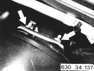
Detach vacuum hose from brake booster. Unscrew upper and lower nuts, and pull out brake booster forward. Installation: Torque values¹). If applicable, replace clamp for vacuum hose.  ¹) See Specifications ¹) See Specifications
|  |
If filter cartridge in brake booster is contaminated, remove cap (1), holder (2), damper (3) and filter (4). Installation: First clean damper (3) and filter (4). | 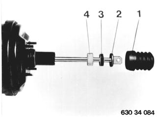 |
When Replacing: Detach tandem brake master cylinder from brake booster. Installation: Torque values¹).  ¹) See Specifications ¹) See Specifications
| 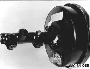 |
Installation: Check rubber ring (1). A rubber ring not providing a perfect seal will prevent building up vacuum. | 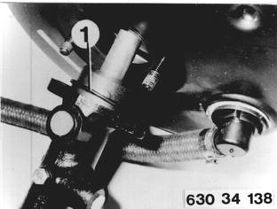 |
Vehicles after change point in 1982 REMOVING AND INSTALLING BRAKE BOOSTER WITH BRAKE MASTER CYLINDER 1 Pump 2 Oil tank 3 Power flow regulator 4 Hydraulic reservoit 5 Steering 6 Hydraulic booster 7 Tandem master cylinder 8 Brake force regulator Description of Entire H 31 System The power flow regulator diverts a small flow (approx. 0.7 ltr. or 1.4 pints) from the power steering operating circuit for the power assisted brake system. It charges the hydraulic reservoir in a high pressure range without impairing the function of power steering. The pressurized hydraulic oil volume is supplied to the booster for the sake of power assistance and is applied by operating the connected standard tandem master cylinder. Should the power steering pump fail, the hydraulic reservoir has sufficient reserve pressure to permit many full stop braking actions. After using up this pressure reserve, brake operation greater force will be required on the brake pedal. | 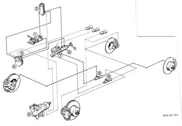 |
Function Test: Operate brake pedal 20 times with engine stopped. Hold brake pedal down and start engine. System is okay, if brake pedal gives. If brake pedal does not give, the power steering pump, power flow regulator, hydraulic reservoir or hydraulic brake booster could be defective. | |
Removing and Installing Brake Booster with Brake Master Cylinder: Discharge hydraulic reservoir by operating brake pedal about 20 times with same force required for full stop braking action with engine stopped. Draw off brake fluid through supply tank with a syringe reserved exclusively for brake fluids. | 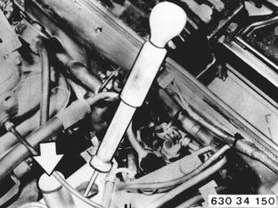 |
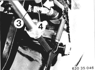
Remove and install instrument panel trim at bottom left 51 45 180. Lift off clip (3) and remove pin (4) on piston rod after disconnecting spring.  51 45 180 51 45 180
|  |
Pull off brake fluid tank. Installation: Check rubber seal. | 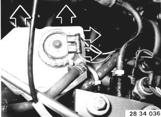 |
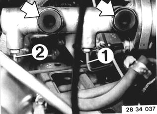
Disconnect brake lines. 1 Front right and rear left 2 Front left and rear right Installation: Tightening torque*. Bleed brakes 34 00 046.  * See Specifications * See Specifications 34 00 046 34 00 046
|  |
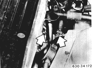
Detach hydraulic hoses on brake booster. Installation: Make sure that all pipe and hose connections are clean before connecting. Tighten return live with Special Tool 34 3 153 and pressure line with Special Tool 34 3 152, both in conjunction with a torque wrench. Tigtening torque*.  * See Specifications * See Specifications
|  |
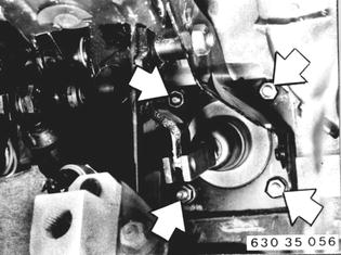
Detach brake booster on pedal assembly base. Remove brake booster and brake tandem master cylinder. Installation: Tightening torque*.  * See Specifications * See Specifications
|  |
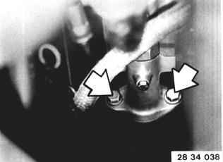
Detach master cylinder on brake booster to replace brake booster. Installation: Tightening torque*.  * See Specifications * See Specifications
|  |
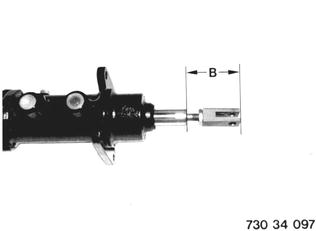
Installation: Detach pivot on brake booster. Attach pivot on new brake booster and adjust to same distance B. If necessary, check distance A on brake pedal in installed state (see 35 21 000).  35 21 000 35 21 000
|  |
BMW 628csi - M635csi (M6)»34 - Brakes»34 33 000 - Brake booster with tandem master cylinder - removing and installing