Vehicles before change point in 1982 REMOVING AND INSTALLING TANDEM BRAKE MASTER CYLINDER Description of Function: Depressing brake pedal moves piston (1) and (4) forward. Primary cups (2) and (5) pass over compensation bores (3) and (6). There is now equal pressure in chambers A and B. Chamber A acts on rear wheel brakes. Chamber B acts on front wheel brakes. Brake pedal travel increases considerably when a brake circuit fails. If second brake circuit fails, piston (4) in chamber B without pressure in pressure is pressed against tandem master cylinder housing by piston (1) via pressure built up in chamber A and in this manner the first brake circuit functions. If first brake circuit fails, piston (1) in chamber A without pressure is pressed against spring cap (7) and the second brake circuit has full effect by way of chamber B. | 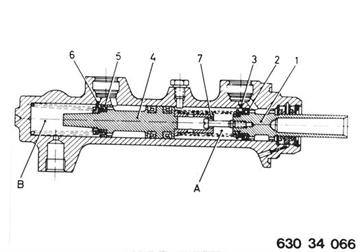 |
 |
|
 |
|
Unscrew nuts and lay back holder with attached parts. Hoses and attached parts remain connected. | 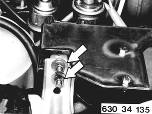 |
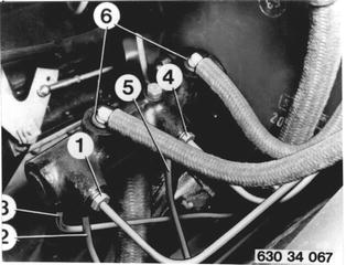
Remove and install air cleaner. Detach hoses at tandem master cylinder and tie them up. Important: Don´t spill fluid out of pipe elbow - remove carfully by pulling up. If rough treatment is applied, pipe could break in bend. Make sure that sealing plugs (6) fit properly in tandem master cylinder. Detach brake lines. 1 Front, right...............) 2 Front, left.................) 1st brake circuit 3 Rear wheel brakes..) 4 Front, right...............) 5 Front, left.................) 2nd brake circuit Installation: Tighten to specified torque¹).  ¹) See Specifications ¹) See Specifications
|  |
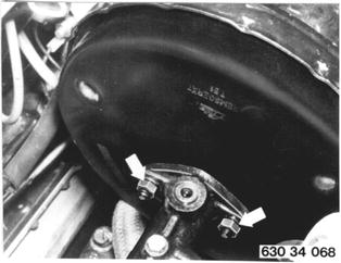
Unscrew master cylinder at brake booster. Installation: Tighten to specified torque¹).  ¹) See Specifications ¹) See Specifications
|  |
Installation: Check rubber ring (1). If rubber ring does not provide a perfect seal, vacuum will not build up. | 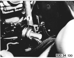 |
Vehicles after change point in 1982 REMOVING AND INSTALLING BRAKE MASTER CYLINDER Description: Operating the brake pedal will move pistons (1 and 4) forward. Primary cups (2 and 5) slide over compensation bores (3 and 6). Now there is equal pressure in chambers A and B. Diagnal Dual Circuit System: Chamber A serves right front and left rear. Chamber B serves left front and right rear. If a brake circuit fails, the brake pedal travel will increase considerably. If the second brake circuit fails, the pressure building up in chamber A will act on piston (1) to move piston (4) in the pressureless chaber B against the tandem brake master cylinder housing and restore function of the first brake circuit. If the first circuit fails, piston (1) will be pressed against spring cap (7) in pressureless chamber A and the second brake circuit will function normally via chamber B. |  |
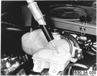
Draw off brake fluid through tank with a syringe, pulling out float housing for this purpose. | 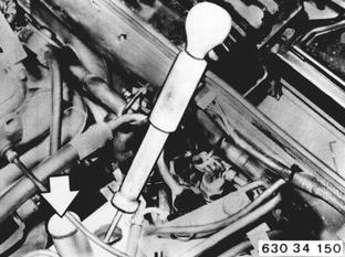 |
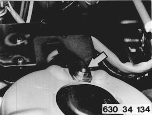
Pull off brake fluid tank. Installation: Check rubber seal. | 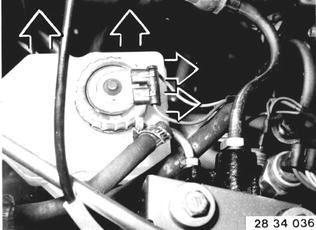 |
Disconnect brake lines. 1. Front right and rear left 1st brake circuit 2. Front left and rear right 2nd brake circuit Installation: Tightening torque*. Bleed brakes 34 00 046.  34 00 046 34 00 046
| 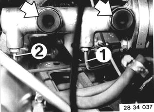 |
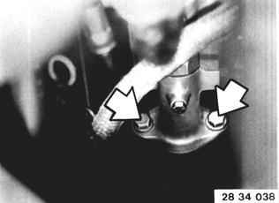
Detach tandem brake master cylinder at brake booster. Installation: Tightening torque*. When replacing, make sure master cylinder has correct diameter. Note: Use correct master cylinder for cars with ABS (these cylinders are not to be overhauled).  * See Specifications * See Specifications
|  |
BMW 628csi - M635csi (M6)»34 - Brakes»34 31 000 - Tandem brake master cylinder - removing and installing