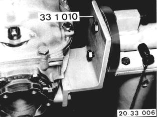
Vehicles after change point in 1982 REPLACING BEARINGS FOR DRIVE PINION - Final Drive Removed - See 33 10 010 in microfilmed repair manual for cars beginning with 1985 models for information on removing final drive. Mount final drive on Special Tool 33 1 010. Drain oil. Unscrew case cover. Installation: Replace gasket. Tightening torque*. Pour in oil - oil volume*. See Group 33 in Operating Material Binder for approved oil grade.  33 10 010 33 10 010 * See Specifications * See Specifications
|  |
Pry off drive flanges with a tire iron. | 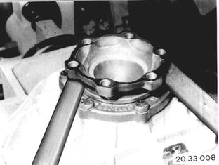 |
Installation: Place round wire snap ring (1) in groove of differential case prior to installation of drive flange in such a manner, that both ends of snap ring are recessed in groove. This prevents lateral bending of snap ring. Press in drive flange by hand and turn slightly, until snap ring is heard to engage. Replace stretched snap rings. | 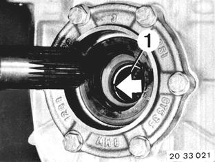 |
Punch mark both bearing caps. Unscrew bolts of both bearing caps and take off bearing caps (turn if necessary, since seals suck tight). Important! Don´t mix up bearing caps and shims. If necessary, fasten shims on bearing caps with pieces of wire. Installation: Tightening torque*.  * See Specifications * See Specifications
| 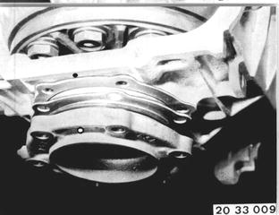 |
Axial preload force (4000 N = 882 lbs.) of differential bearings and backlash of ring gear/ pinion are adjusted with shims (1). | 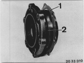 |
Remove complete differential case. Important! Don´t bend the pulse spider. | 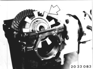 |
Lift out lockplate. | 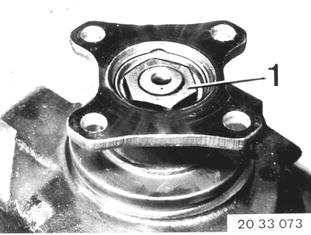 |
Hold input flange with Special Tool 23 0 020 and unscrew the collar nut. | 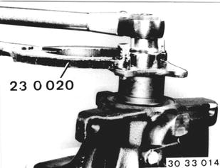 |
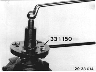
Pull off input flange with Special Tool 33 1 150. The specified friction torque* is given for new bearings and friction torque of old bearings does not have to be measured.  * See Specifications * See Specifications
|  |
Press out drive pinion. Caution! Be careful not to damage threads. | 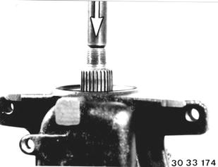 |
Pull out front bearing outer race with Special Tool 33 1 350. 1 Spreader 2 Front bearing outer race 3 Puller bell housing 4 Pressure bolt | 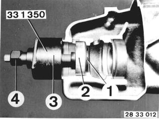 |
Pull out rear bearing outer race with Special Tool 33 1 360. Puller consists of: Puller head.................. 33 1 361 Threaded spindle.........33 1 362 Bearing bridge............. 33 1 356 Pressure nut................ 33 1 363 Important! Shim (X) is located underneath the rear bearing outer race. It will be needed again for the block distance adjustment. | 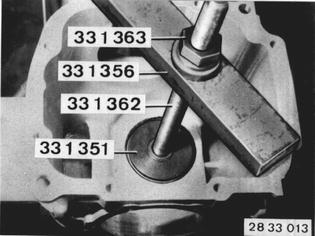 |
Install old shim (X) in front of the rear bearing outer race. Pull in bearing outer races with Special Tool 33 1 360. Puller consists of: Puller disc for front outer race..... 33 1 373 Puller disc for rear outer race...... 33 1 365 Threaded spindle........................ 33 1 362 Pressure nut................................ 33 1 363 Nut.............................................. 33 1 354 | 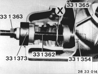 |
Pull tapered roller bearing off of drive pinion with Special Tool 33 1 300. Caution! Be careful not to damage the pinion - use soft aluminum jaws or pieces of wood. | 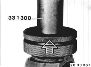 |
Press new tapered roller bearing on to drive pinion with Special Tool 33 1 020. Important! Always only use both bearings of same make. | 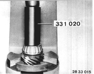 |
The drive pinion is installed with new tapered roller bearings, but without clamping sleeve, to determine correct thickness of shim (X). | 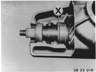 |
Install drive pinion in rear bearing outer race. Pull front tapered roller bearing on to drive pinion with Special Tool 23 1 300 in conjunction with a spacing sleeve. | 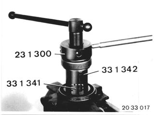 |
Mount input flange. Adjust the friction torque of the drive pinion bearings to 250 Ncm (22 in.lbs.) by tightening the collar nut carefully. |  |
Important! Measure friction torque at intervals during the tightening procedures with Special Tool 00 2 000. | 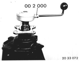 |
Block Distance of Drive Pinion: Mount dial gage in Special Tool 33 1 461. Place Special Tool 33 1 461 with dial gage on Special Tool 33 1 462 and set dial gage to 0 (zero) with preload. | 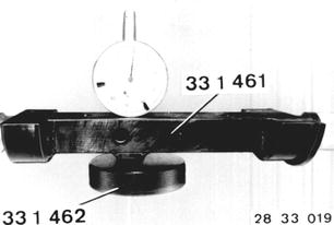 |
Place Special Tool 33 1 462 on drive pinion. Place Special Tool 33 1 461 in case. Determine value Y: Basic distance......... C = 11.50 mm (0.453´´) Gage thickness....... B = 9.50 mm (0.374´´) | 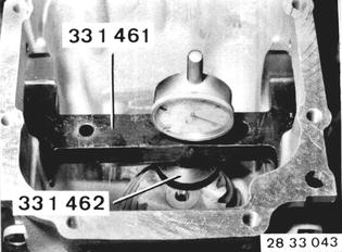 |
Examples for Determination of Correct Shim Thickness (X) Example I C........................................ 11.50 mm (0.453´´) e+........................................ 0.10 mm (0.004´´) _____________________________________ C nominal.............................11.60 mm (0.457´´) Y measured on dial gage....... 1.90 mm (0.075´´) + gage thickness................... 9.50 mm (0.374´´) _____________________________________ C actual................................11.40 mm (0.449´´) C nominal..............................11.60 mm (0,457´´) C actual..............................- 11.40 mm (0.449´´) _____________________________________ a.............................................0.20 mm (0.008´´) Gage thickness A...................4.10 mm (0.161´´) - a...........................................0.20 mm (0.008´´) _____________________________________ Shim thickness (X)..................3.90 mm (0.153´´) If C nominal is larger than C actual, "a" is subtracted (-) from shim thickness X. Example II C...........................................11.50 mm (0.453´´) e-............................................0.10 mm (0.004´´) _____________________________________ C nominal..............................11.40 mm (0.449´´) Y measured on dial gage........2.20 mm (0.087´´) + gage thickness....................9.50 mm (0.374´´) _____________________________________ C actual.................................11.70 mm (0.461´´) C actaul.................................11.70 mm (0.461´´) C nominal.............................- 11.50 mm (0.453´´) _____________________________________ a.............................................0.20 mm (0.008´´) Gage thickness A...................3.90 mm (0.153´´) +a...........................................0.20 mm (0.008´´) _____________________________________ Shim thickness (X)..................4.10 mm (0.161´´) If C nominal is smaller than C actual, "a" is added to shim thickness X (+). The permissible tolerances for distance (X) result from the tolerances for shim thicknesses which are available in steps from 0.01 to 0.03 mm (0.0004 to 0.0012´´). | 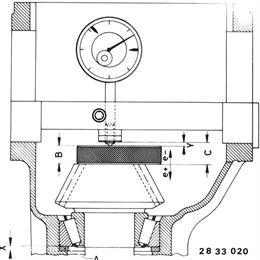 |
Remove drive pinion after determining the thickness of shim (X). Important! Note make of bearings - this is required for determination of friction torque. |  |
Remove rear bearing outer race and install again with shim (X) of determined thickness. |  |
Install drive pinion with new clamping sleeve (2). | 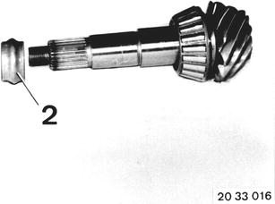 |
Dip shaft seal in final drive gear lube and drive in flush with Special Tools 33 1 270 and 00 5 500. | 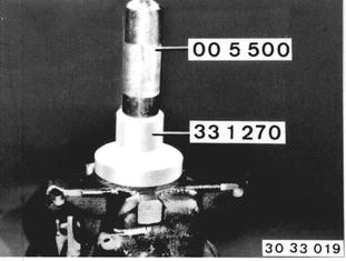 |
Press (don´t pull) input flange on to the input shaft with Special Tool 23 1 300. Axial preload force (5000 N = 1102 lbs.) of drive pinion bearings can be determined with help of the friction torque. | 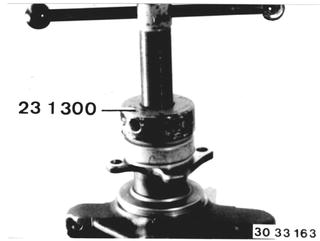 |
Tighten input flange with the collar nut in steps, measuring the friction torque after each step (see below). |  |
Measure friction torque* with Special Tool 00 2 000 and a suitable wrench socket. Important! The relation between friction torque and preload force differs depending on the make of bearings. Take the specified friction torque from the pinion bearing table* and add 20 Ncm (2 in.lbs.) for the new shaft seal.  * See Specifications * See Specifications
|  |
Install differential. Install side covers as marked with corresponding washers (1) and new O-rings (2). Tighten bolts uniformly. Tightening torque*.  * See Specifications * See Specifications
|  |
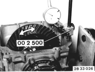
- Backlash/Tooth Contact Pattern Adjustment - Mount Special Tool 00 2 500 and measure backlash* with dial gage. Important! The tooth contact pattern is always most important for a perfectly adjusted pinion/ring gear set.  * See Specifications * See Specifications
|  |
To check the tooth contact pattern, coat the ring gear teeth with printer´s ink, turn in both directions several times and stop ring gear suddenly with a piece of hard wood. | 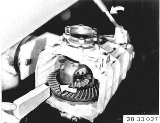 |
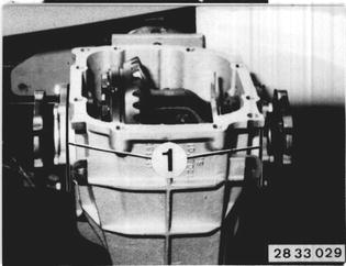
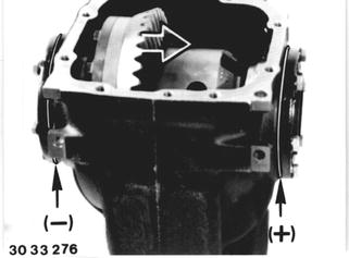
Correct backlash* and tooth contact pattern by changing the thickness of both shims (1). If backlash is excessive, use a thinner shim on the ring gear end. If backlash is too small, use a thicker shim on the ring gear end. An axial displacement of the ring gear by 0.01 mm (0.0004´´) will cause a change in backlash of 0.076 mm (0.0003´´). Important! The total thickness of both shims must not be changed.  * See Specifications * See Specifications
|  |
If a thinner or thicker shim is required to correct the tooth contact pattern, the total thickness must be corrected with the second shim, since otherwise the friction torque of bearings would be changed again. See "Replacing Differential Bearings" in 33 11 731 for information on determining friction torque of differential bearings.  33 11 731 33 11 731
|  |
See "Replacing Drive Pinion and Ring Gear" in 33 12 551 for general information on tooth contact pattern adjustments.  33 12 551 33 12 551
| |
Pull out old shaft seals with Special Tool 00 5 000 or 00 5 010 in conjunction with a thrust piece. | 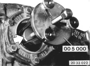 |
Installation: Dip new shaft seals in final drive gear lube. Drive in shaft seals against the stop with Special Tools 33 1 230 and 00 5 500. Replace a drive flange with seriously scored bearing surfaces. | 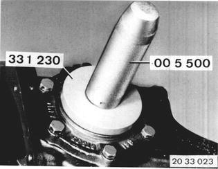 |
Drive in new lockplate with Special Tools 33 4 050 and 00 5 500. | 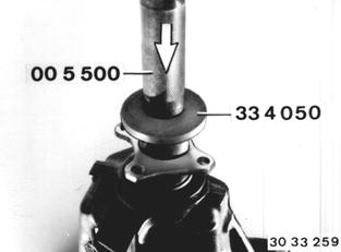 |