Vehicles after change point in 1982 DISASSEMBLING/ASSEMBLING STEERING COLUMN - STEERING COLUMN ASSY. REMOVED - Take off headlight dimmer and windshield wiper switch. | 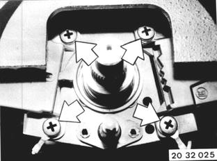 |
Remove collar (1). Installation: Cut in collar (1) must lock snap ring (2). | 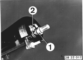 |
Take off flasher relay with holder. Pull off wires for horn contact. Unscrew bolt. | 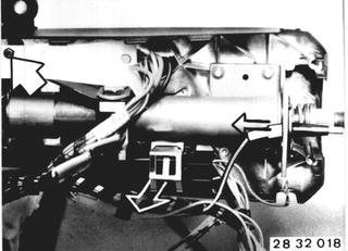 |
Remove shear-off screws (2) with a chisel or similar tool. Remove steering lock plate (1). | 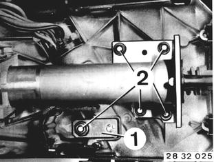 |
Unscrew set screws. Installation: Lock set screws with clear lacquer. | 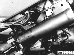 |
Press casing upper section away from steering tube. Turn ignition key in "start" direction and pull out complete steering lock. | 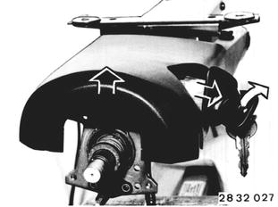 |
Remove ignition switch. | 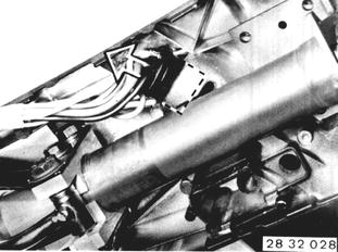 |
Unscrew bolts and take steering outer tube off of casing upper section. | 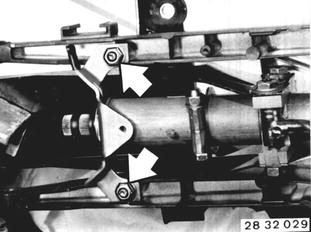 |
Remove snap ring (1), washer (2), spring (3) and ring (4). Installation: Stem of ring (4) faces bearing. |  |
Installation: Mount snap ring (1) with Special Tools 32 3 052 and 32 3 050. | 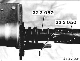 |
Pull steering spindle (1) and lower bearing (2) out of outer tube. | 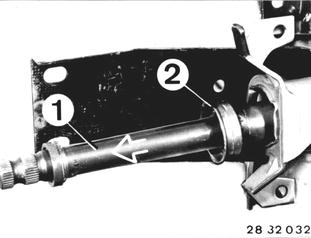 |
Take off snap ring (1), collar ring (2), ring (3) and bearing (4). Installation: Stem of ring (3) faces bearing. Snap ring (1) locks in recess of collar ring (2). | 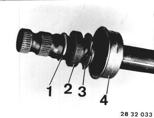 |
Installation: Push steering spindle into outer tube. Knock in bearing with Special Tool 00 5 550. Install ring (3) and collar ring (2). Mount snap ring (1) with Special Tools 32 2 052 and 32 3 050. | 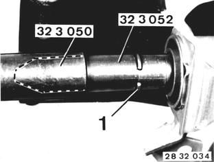 |
Lift upper steering spindle bearing out of outer tube with a screwdriver. Installation: Knock in bearing with Special Tool 00 5 550. |  |
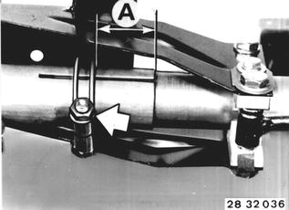
Loosen clamp. Installation: Check distance (A) from clamp to end of outer tube. A = 42 to 45 mm (1.653 to 1.772´´). Tighten clamp only after screwing outer tube on casing upper section. Tightening torque*.  * See Specifications of Group 32 * See Specifications of Group 32
|  |
Bend open lockplate. Unscrew bolts (1 ... 6). Bolt (1) = left-hand threads. | 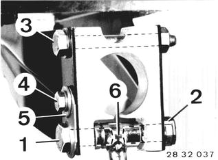 |
Clamp Installation Procedures: (keep to sequence) 1.) Screw in bolt (2) with lockplate and tighten to specified torque* and lock. Lever (6) is located in center of clamp in "OFF" position. 2.) Screw in left bolt (1) and tighten to specified torque*. Lever (6) in "OFF" position. 3.) Tighten bolt (3) to specified torque*. Lever (6) in "OFF" position. 4.) Bolt lockplate (5) with bolt (4).  * See Specifications * See Specifications
|
BMW 628csi - M635csi (M6)»32 - Steering and wheel alignment»32 31 091 - Steering column - dissamble and assemble (steering column assy. removed)