 |
|
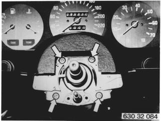
Pull off plug for horn contact. Loosen wire holding clip. | 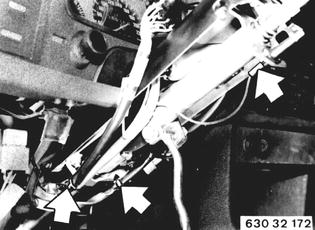 |
Unscrew headless stud and pull out ignition switch. Place wire harness to one side. | 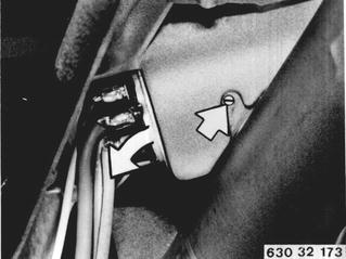 |
Installation: Remove ignition key. Turn ignition switch to left stop. Insert ignition switch and install headless stud. Lock headless stud with paint. | 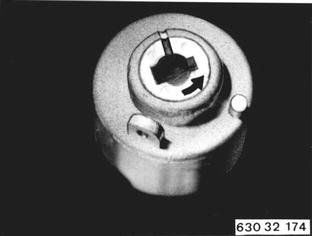 |
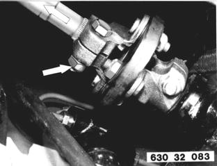
Unscrew steering spindle at bottom from universal joint. Installation: Make sure screw is located in locking groove. Note lockwasher for version without nut. Tightening torque¹).  ¹) See Specifications ¹) See Specifications
|  |
 |
|
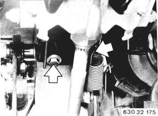
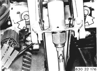
Loosen screws. Take hold of steering spindle at lower end and pull out steering spindle with steering column. Installation: The two screws have large washers. Lubricate seal at firewall with Longterm 2. Tightening torque¹).  ¹) See Specifications ¹) See Specifications
|  |
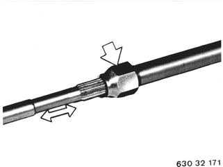
Important: Don´t disassemble upper and lower steering spindle sections. If a steering spindle was disassembled or the nut loosened, tighten nut enough that specified pushing torque¹) can be reached.  ¹) See Specifications ¹) See Specifications
|  |
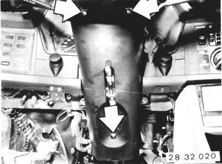 |
|
Disconnect central electric plugs. | 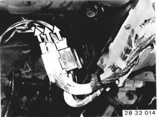 |
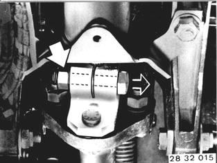
Remove bolt and pull coupling off of upper steering spindle. Installation: Bolt must be in the locking groove. Replace self-locking nut. Tightening torque*.  * See Specifications of Group 32 * See Specifications of Group 32
|  |
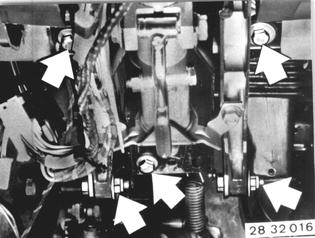
Unscrew bolts and remove steering column. Installation: Replace self-locking nuts. Tightening torque*.  * See Specifications of Group 32 * See Specifications of Group 32
|  |
BMW 628csi - M635csi (M6)»32 - Steering and wheel alignment»32 31 090 - Steering column - removing and installing