DISCHARGING AND CHARGING AIR CONDITIONER Safety Precautions for Handling Refrigerant: The air conditioner is filled with a safety refrigerant (Frigen 12). Although this product at normal temperatures is not poisonous, non-inflammable and not explosive regardless of ratio mixed with air, several important precautions deserve your attention. Avoid any form of contact with liquid or gaseous refrigerant. Proctect hand with gloves and eyes with safety goggles when working on the refrigerant circuits of an air conditioner. Refrigerant on skin will cause frostbite. Wash off pertinent areas of skin with water thoroughly. This also applies when refrigerant gets in the eyes, but then also go to a physician without delay. Frigen is heavier than air, so that this refrigerant should not be drained in closed rooms. There is danger of asphyxiation in work pits in particular, since the gas is colorless and odorless. Always turn on available extraction systems. Don´t weld on or near a charged air conditioner regardless of circumstances. This would cause excessive pressure and in turn the danger of explosion. Frigen will also decompose at high temperatures and flame heat. Decomposition products are injurious to health. Store full refrigerant bottles that they are not subjected to direct sunshine or other sources of heat (max. 45°C / 113°F). | |
Discharging and Charging Air Conditioner: Refer to operating instructions supplied with charging equipment. Major Operations: 1. Connecting charging equipment 2. Discharging (at least 1/2 hour) 3. Checking for leaks 4. Charging with Frigen 12 Volume: 1000 p Important: Don´t start engine while charging! 5. Checking function of air conditioner: a) Solenoid coupling on compressor working? b) Extra fan running (direction)? c) Bubbleless circulation of refrigerant? (sight glass on drier) | 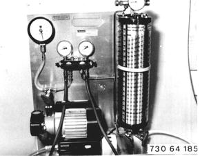 |
Function of Refrigerant Circuit Switching on the air conditioner starts up the refrigerant circuit, i.e. power is supplied to the solenoid coupling coil and the magnetic field produced by this action pulls the armature coupling plate which is firmly connected with the compressor shaft, next to the inner plate running freely on the same shaft. In this manner the swash plate compressor is driven by friction force. The swash plate compressor, a major component of the air conditioning system, increases the pressure of the refrigerant vapors.The refrigerant vapors are drawn in on the intake side of the compressor. The refrigerant is then compressed by three double-action pistons, which are arranged axially around the input shaft, whereby the vapor temperature rises. The high pressure vapors travel through a high pressure line to the condenser on the face of the engine oil cooler. The hot refrigerant will be cooled by the wind from driving and an extra fan. When reaching a certain temperature the refrigerant vapors condense, becoming liquid and cooler. The high pressure refrigerant is passed on to the refrigerant tank/drier. The drier will remove moisture and possibly acids from the refrigerant, however this only to an extent of approx. 6 to 10 grams. The refrigerant continues from the drier to the block valve (expansion valve). The block valve is a separating point in the system. The expansion valve meters the flow of refrigerant. The injection rate will depend on the temperature and pressure at outlet of the evaporator. In the evaporator the refrigerant will be relaxed, it evaporates and cools off considerably. The fresh air or ambient air flowing past a cold evaporator, supported by a blower, will be cooled accordingly and supplied to the passenger compartment via nozzles. The vaporized refrigerant will be drawn in by the compressor again to close the refrigerant circuit. Moisture in the fresh or ambient air, which flows around the evaporator, condenses on the cold plates. The condensation water is discharged from the evaporator via two rubber hoses on the transmission tunnel and could cause a puddle of up to two liters (2 quarts) underneath a parked car depending on the humidity. This is completely normal and must not be taken as an indication of a defective system. It could happen that the condensation will freeze on the plates of the evaporator. A temperature switch with a capillary sensor protects the evaporator from icing up and will switch off the air conditioner when ice begins to form. This will stop the refrigerant circuit and the evaporator can thaw. The temperature switch will provide power flow after thawind, the soleniod will be activated and the refrigerant circuit is started from new. | |
Refrigerant Circuit 1 Compressor 2 Solenoid 3 Condenser 4 Refrigerant tank 5 Drier 6 Pressure switch 7 Sight glass 8 Safety glass 9 Expansion valve 10 Evaporator 11 Temperature switch 12 Temperature sensor High pressure, liquid High pressure, gas Suction pressure, liquid Suction pressure, gas | 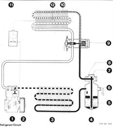 |
AIR CONDITIONER WIRING DIAGRAM Key to Wiring Diagram 1 Power supply box a) Plug to power supply box b) Releasing relay 2 Fuse 2 x 25 A 3 Extra fan relay stage II 4 Temperature switch 5 Ground 6 Extra fan relay stage I 7 Diode 8 Extra fan motor plug 9 Extra fan motor 10 Battery 11 Ignition switch plug 12 Ignition switch 13 Ground 14 Plug for extra equipment 15 Power supply connection 16 Rear window defogger switch 17 Ground 18 Magnetic clutch for compressor 19 Plug 20 Clock 21 Instrument light I 22 Instrument light II 23 Instrument light III 24 Instrument light IV 25 Heater/air conditioner microswitch 26 Temperature control switch 27 Plug, 2-pin 28 Speed control 29 Relay I 30 A/C blower plug 31 A/C blower 32 Heater blower plug 33 Heater blower 34 Relay II 35 Diose Color Codes BL = blue BR = brown GE = yellow GN = green GR = gray RT = red SW = black VI = violet WS = white TR = transparent | 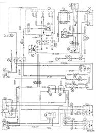 |
1 = Wire size in mm² 2 = Basic color 3 = Identification spiral 4 = 5 = Terminal designation 6 = Terminal connection (galv. wire ends) 7 = Terminal connection (wire connnectors) 8 = Round male plug 9 = Flat male plug 10 = Round female plug 11 = Flat female plug 12 = Additional parts 13 = Standard parts 14 = Ground 15 = Solder point or connector | 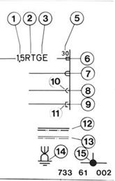 |
DISCHARGING AND CHARGING AIR CONDITIONER Safety Precautions for Handling Refrigerants The air conditioning system must be filled with a safety refrigerant (Frigen 12). Although this refrigerant is non-toxic, non-flammable and non-explosive in any mixture radio with air at normal temperatures, it can still be dangerous unless the appropriate safety precautions are observed. Avoid any contact with liquid or gaseous refrigerant. When working on the refirgerant circuit of an air conditioner protect hands with gloves and eyes with goggles. Refrigerant on the skin will cause frostbite. Wash off pertinent parts of the body with cold water thoroughly. If refrigerant gets in the eyes, also rinse out with water and then contact a physician immediately. Frigen is heavier than air and therefore should not be discharged in closed rooms. Especially in working pits there would be an acute danger of asphyxiation, which would not be noticeable since the gas has no color or odor. Turn on available air extraction systems. Never perform welding work on a discharged air conditiioner or in the vicinity. The pressure which would occur could lead to an explosion. In addition Frigen decomposes at high temperatures or when exposed to an open flame. The decomposed products are injurious to health. Store full refrigerant cylinders that they are not subjected to direct sunshine or other sources of heat (max. temperature 45°C / 113°F). | |
Vehicles after change point in 1982 Discharging and Charging Air Conditioner: Conform with operating instructions supplied with pertinent charging equipment. Major Procedures: 1) Connecting charging equipmet 2) Discharging (time depends on condition of air conditioner) 3) Flushing with refrigerant 4) Discharging 5) Charging with refrigerant . volume* Caution! Do not start engine while charging. 6) Checking function of air conditioner  * See Specifications * See Specifications
| 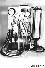 |
Check condition of the discharging and charging station before operation. Check level and grade of oil in the compressor. Also refer to the operating instructions supplied with the charging station. Caution! Never leave high pressure on pressure gage (2) during the operating procedures - danger of destruction. Note: The air conditioner can also be discharged and charged with only one charging hose (high or low pressure). However, working with a valve core remover and two charging hoses will speed up discharging and charging procedures. Absolute cleanliness is required for the performance of work on an air conditioner. Wear protective clothing! Close all valves of the discharging station prior to starting the procedures. The following procedures are only applicable with the illustrated charging station. | 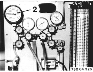 |
Remove the protective cap. Connect blue charging hose (1) on the low pressure side (thick pipe) of the air conditioner. | 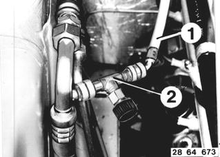 |
Remove the protective cap. Connect red charging hose (1) on the high pressure side (thin pipe or drier) of the air conditioner. | 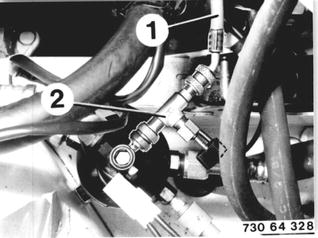 |
Connect the refrigerant cylinder (2) and charging hose (16) with charging valve (1). Charging valve (1) remains connected until the charging cylinder has been filled. | 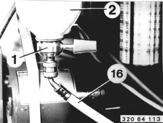 |
Open valves (4, 6 and 22). Turn on the pump with switch (12) and discharge the charging station. Close valve (22) and open valves (5 and 23). Discharge the air conditioner. | 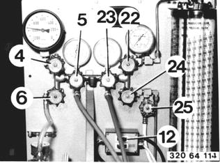 |
Open valve (25). | 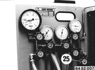 |
Open charging valve (1) and fill the charging cylinder with refrigerant while the air conditioner is still being discharged. Type and amount of refrigerant*.  * See label in engine compartment * See label in engine compartment
| 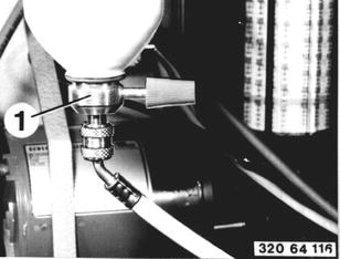 |
To fill the charging cylinder, unscrew protective cap (1) and apply pressure on the valve core to let pressure escape from the charging cylinder. This is necessary so that refrigerant can flow into the charging cylinder. | 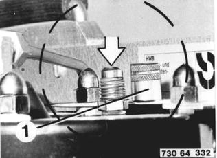 |
Close charging valve (25) and operate the heater with switch (13) after finishing the charging procedure. | 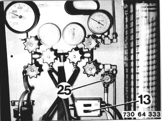 |
Read the rising pressure in the charging cylinder on gage (20) and set the same pressure (e.g. 5.6 bar/80 psi) on the volume scale (18). The amount of refrigerant in the charging cylinder can now be read on the volume scale. The heater can be switched off after reaching the charging pressure of 4.9 to 9.1 bar (70 to 129 psi). | 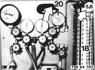 |
After Finishing Discharging: Close shutoff valve (6). Mark the red indicator (A) with the displayed value. The air conditioner does not have moisture or leaks, if the pressure does not rise. Switch off the vacuum pump. | 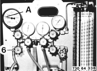 |
Detecting Leaks: Close valve (6). Close vacuum valve (4). Switch off the vacuum pump. Open charging valve (22) abaout 1 second and then close it again. | 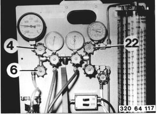 |
Calibrate leak detector (1) to the operating instructions. Check air conditioner for leaks with leak detector (1). Eliminate any leaks. Note: Always look for a leak underneath a possible leak point, since refrigerant is heavier than air. | 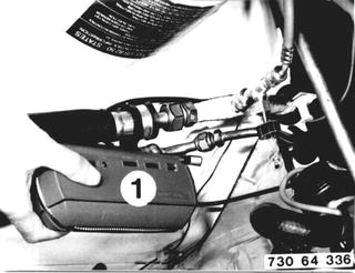 |
Charging the System: Close vaccum valves (4 and 5). Open liquid valve (24) and let the correct amount* of refrigerant flow into the system.  * See label in engine compartment * See label in engine compartment
| 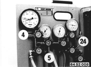 |
Shut the liquid valve (24) when the system has the correct amount* of refrigerant. Disconnect hoses and screw on the protective caps.  * See label in engine compartment * See label in engine compartment
|
BMW 628csi - M635csi (M6)»64 - Heating and air conditioning system»64 50 009 - Air conditioner - discharging and charging