Vehicles after change point in 1982 SIMULATOR FOR CHECKING INSTRUMENT CLUSTERS 1 ON / OFF switch 2 Power supply control lamp 3 Selector switch 4 Distance pulse control lamp 5 Tachometer changeover switch 6 Starting simulation button 7 Display range running off knob 8 Oil service reset button 9 Inspection reset button 10 SI running off and adjusting button | 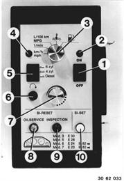 |
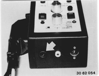 |
|
1. Checking Complete Instrument Cluster. Plug connection plate (1) of '5/6/7' series wire harness on instrument cluster and secure with clamps (2). Caution! Be careful not to bend the spring contacts when mounting the connection plate. Connect blue and white plugs of wire harness on the instrument cluster. | 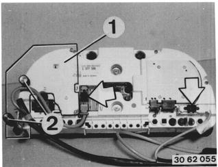 |
Connect lead (1) and power supply lead (2) on simulator. Connect red terminal (3) on B + and black terminal (4) on B - of a 12 V battery. Turn on simulator with switch (1). The red control lamp will not come on with battery voltage of less than 11.5 V; the simulator is not ready for use. Note: Use a different battery or the supplied power unit (Order No. 81 12 9 424 203)! | 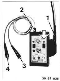 |
1.2 Checking 1.2.1 Speedometer Set selector switch (3) to km/h or mph, and turn knob (7) against left stop; speedometer needle passes through the display range. Note: The simulator is designed for speedometers with a display range of 280 km/h. If the display range of speedometer is smaller, it could happen that after reaching the final display value and increasing the frequency with knob (7) the needle would fall back to an undefined display value. When increasing the frequency again, the needle would start from this display value and pass through the display range. | 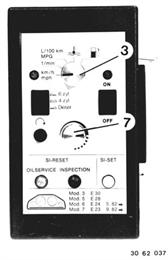 |
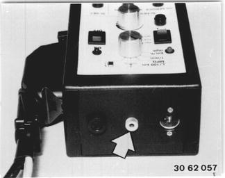
The set frequency can be measured on the yellow jack with a BMW Service Tester (multimeter 14) - see operating instructions of the BMW Service Tester. Yellow connection terminal FREQ in + in yellow jack; black connection terminal FREQ in - on B - of battery. Test values: See Specifications  See Specifications See Specifications
|  |
1.2.2 Tachometer Selector switch (3) set to 1/min (rpm). Turn knob (7) against left stop; needle of tachomewter points to 0. Set switch (5) to correct position! Tachometer for: 6 cylinder engines = 6 zyl 4 cylinder engines = 4 zyl diesel engines = Diesel Turn knob (7) clockwise slowly; needle of tachometer passes through the display range. The green LEDs go out when exceeding a speed of 600 rpm. Note: The simulator is designed for tachometers with a display range of 8000 rpm. When the tachometer has a 5000 rpm display range, it could happen that after reaching the display value and increasing the frequency with knob (7) the needle will fall back to an undefined display value. When increasing the frequency even more, the needle starts from this display value and passes through the display range again. | 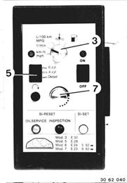 |
The set frequency can be measured on the yellow jack with a BMW Service Tester (multimeter 14) - see operating instructions of a BMW Service Tester. Yellow connection terminal FREQ in + in yellow jack; black connection terminal FREQ in - on B - of battery. Test values: See Specifications  * See Specifications * See Specifications
|  |
1.2.3 Economy Control (EC) Selector switch (3) set to L/100 km or MPG. Press button on connection plate and hold it pressed in! | 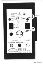 |
Turn knob (7) against left stop; EC needle points to 0 (for L/100 km) or °° (for MPG). Turn knob (7) clockwise slowly; EC needle passes through display range up to approx. °° (for L/100 km) or up to approx. 0 (for MPG). | 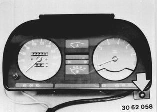 |
1.2.4 Temperature Gage Selector switch (3) set to temperature. Turn knob (7) against left stop; needle of temperature gage is in the blue range. Turn knob (7) clockwise slowly; needle of temperature gage passes through the display range. Note: Needle deflection takes place only in last third of turning range for knob (7). | 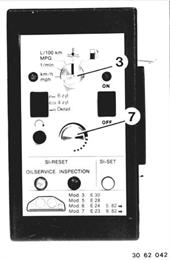 |
1.2.5 Fuel Gage Selector switch (3) set to tank. Turn knob (7) against left stop; needle of fuel gage points to R. Turn knob (7) clockwise slowly; needle of fuel gage passes through the display range. Note: Needle deflection takes place only in last third of turning range for knob (7). | 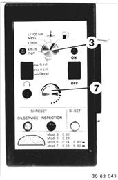 |
1.2.6 Service Interval Indicator Set selector switch (3) to 1/min (rpm). Turn knob (7) against the left stop; needle of the tachometer points to 0. Set switch (5) to correct position!. Tachometer for: 6 cylinder engine = 6 zyl 4 cylinder engine = 4 zyl diesel engine = Diesel The LEDs of SI begin to light up several seconds after switching in (switch set to ON). Turn knob (7) clockwise slowly; the green LEDs go out after reaching a speed of about 600 rpm. Switching the simulator off and on again afterwards will cause the LEDs to light up again in both cases. |  |
The Service Interval Indicator can be reset with buttons (8 and 9). Button 8: reset for OIL SERVICE Button 9: reset for INSPECTION A corresponding interval will be reset by briefly pressing the pertinent button. The period of resetting action is displayed by a lamp in the pertinent button. | 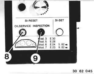 |
The Service Interval Indicator can be adjusted with button (10). Pressing button (10) briefly will cancel the green or set the red LEDs of the Service Interval Indicator. Button (10) may only be tipped briefly for one LED (cancellation)!. | 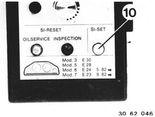 |
Service Interval Indicator Runoff in Time (SI of the 2nd Generation) The diagram to the left shows the runoff for a 2nd generation Service Interval Indicator. Note: The BMW 524 td has two oil service intervals between each inspection interval. Oil Service Intervals: - Resetting "OIL SERVICE" "OIL SERVICE" sign and yellow (possibly red) LED on. Pressing reset button (8) briefly will cancel the indicator. All 5 green LEDs come on. - Resetting "INSPECTION" "INSPECTION" sign and yellow (possibly red) LED on. Pressing reset button (9) longer will cancel the indicator. All green LEDs come on. The time counter is not influenced. The time counter can be reset by pressing the reset button (9) a second time. - Resetting "TIME SYMBOL" The "TIME SYMBOL" and one or more green LEDs on. Pressing reset button (9) longer will cancel the time symbol and time counter. Green LEDs are not influenced! The distance counter can be reset by pressing the reset button (9) a second time. | 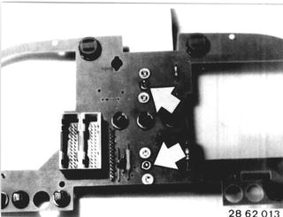 |
2.1 Checking Instruments Separately Connect plug (1) of '5/6/7' wire harness on the adapter for instruments. | 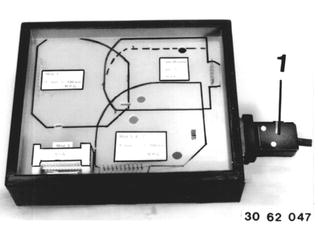 |
Connect lead (1) and power supply lead (2) on simulator. Connect red terminal (3) on B + and black terminal (4) on B - of a 12 V battery. Turn on simulator with switch (1). The red control lamp will not come on with a battery voltage of less than 11,5 V; the simulator is not ready for use. |  |
2.2 Checking Disassemble the instrument cluster - see Group 62. 2.2.1 Speedometer Connect speedometer on adapter (1). Test as described in 1.2.1. | 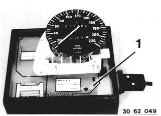 |