| |
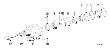
POWER STEERING PUMP ASSEMBLY DRAWING - Code No. 76 71 955
1 Hook-type snap ring
2 Cover
3 O-ring
3.1 Support ring
4 Spring
5 Face plate
6 O-ring
6.1 Support ring
7 Snap ring
8 Rotor set
9 Face plate
10 Dowel pin
11 Housing
12 Radial oil seal
13 Input shaft
|  |
| |
Vehicles after change point in 1982
DISASSEMBLING/ASSEMBLIND
POWER STEERING PUMP
- PUMP REMOVED -
A) Pump Code Number: 7671 955
Absolute cleanliness is essential when working
on power steering pumps.
| |
| |
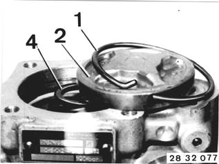
Pull hook-type snap ring (1) out of groove
with a pliers.
Take off cover (2) and spring (4).
|  |
| |
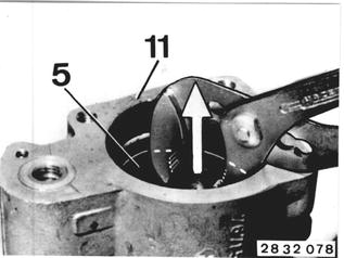
Pull out face plate (5) from housing (11).
|  |
| |
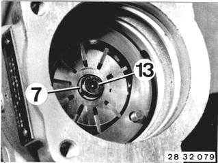
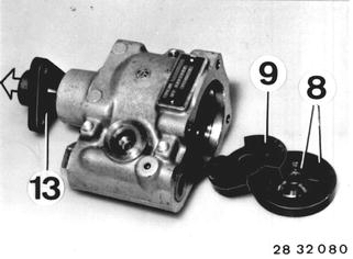
Push rotor on shaft (13) and lift out snap ring
(7).
|  |
| |
Tilt out rotor set (8) and face plate (9).
Pull out input shaft (13).
|  |
| |
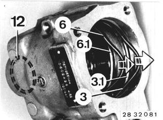
Remove radial oil seal (12) and O-rings (3 an
6).
Support rings (3.1 and 6.1) remain in housing.
Clean all parts thoroughly.
|  |
| |
Assembling:
Lubricate all parts with hydraulic fluid.
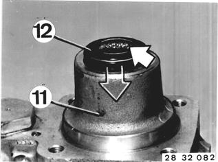
Pack radial oil seal (12) between sealing lip and
dust lip with grease and install seal in housing
(11) with a suitable mandrel (sealing lip faces
in).
|  |
| |
Guide drive shaft (13) into housing (11).
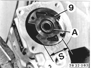
Insert dowel pins (10) in housing bores.
Mount face plate (9) on dowel pins (10) wiht
short side (S) facing valve.
Groove (A) faces cover.
|  |
| |
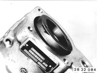
Mount cam ring with cast arrow facing cover
end (arrow shows turning direction of pump)
on dowel pins (10).
|  |
| |
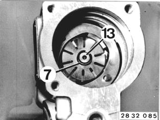
Install rotor with chamfer facing drive end
on shaft (13).
Install snap ring (7) in radial groove of shaft
(13).
Push down on shaft (13) until snap ring (7)
rests in opening of rotor.
|  |
| |
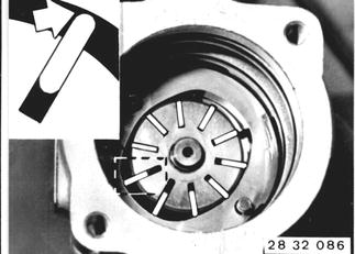
Insert wings with polished, rounded outside
surfaces facing cam ring.
Check that wings move easily.
|  |
| |
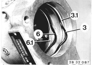
Insert O-rings (3 and 6).
Support ring (3.1) is in front of and support
ring (6.1) behind O-ring.
|  |
| |
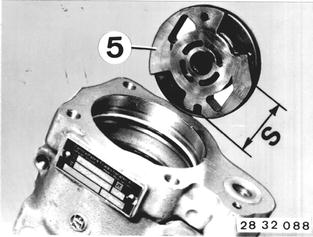
Install face plate (5) on dowel pins (10) with
short side (S) facing valve.
|  |
| |
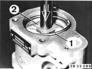
Install spring (4) with large diameter end facing
cover.
Press cover (2) into housing with a hydraulic
press far enough, that hook-type snap ring can
be installed in groove.
|  |
| |
Check operation of power steering pump after
installation.
| |
| |
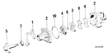
Pump code Number: 7681 955 ...
1 Holder
2 Housing
3 Face plate
4 Rotor
5 Shaft
6 Circlip
7 Seal
8 Seal
9 Guide
10 O-ring
|  |
| |
B) Pump Code Number: 7681 955 ...
Absolute cleanliness is essential when working
on power steering pumps.
| |
| |
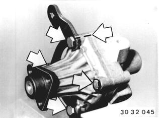
Mark position of holder (1) to pump body (2).
Unscrew bolts and take body apart.
|  |
| |
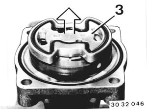
Remove face plate (3).
|  |
| |
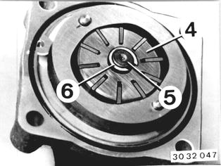
Press rotor (4) on shaft (5) downward.
Remove circlip (6) and pull shaft out of body.
Remove rotor (4) with wings.
|  |
| |
Assembling:
Clean all parts and lubricate with hydraulic
fluid.
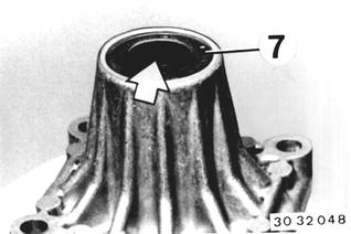
Replace radial oil seal (7) - sealing lip faces in -
and pack space between sealing and dust lips
with grease.
|  |
| |
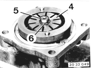
Guide shaft (5) into body.
Install rotor (4) - groove for snap ring faces
up - and insert snap ring (6) in radial groove
of shaft.
|  |
| |
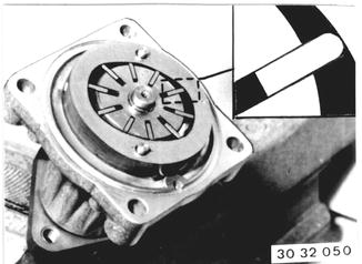
Insert wings with polished, rounded outside
surfaces facing cam ring.
Check that wings move easily.
|  |
| |
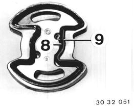
Install seal (8) - wide side facing down - and
place guide (9) in face plate (3).
|  |
| |
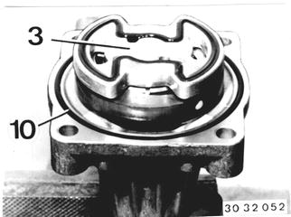
Place face plate (3) on dowel pins.
Replace O-ring (10).
|  |
| |
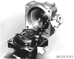
Mount body - check position of bores - and
bolt down with holder.
Tightening torque = 16 to 19 Nm (12 to 14 ft.lbs.).
|  |
| |
After finishing installation, check operation of
power steering pump.
| |